
Pumping unit

A technology of pumping units and sucker rods, which is applied to mechanical equipment, mining fluids, boreholes/well components, etc., can solve the problems of small output power and waste of motor power, and achieve the effect of reducing power

Inactive Publication Date: 2007-10-03
WUXI DEPULAI GASOLINEEUM MACHINERY
View PDF1 Cites 5 Cited by
  • Summary
  • Abstract
  • Description
  • Claims
  • Application Information

AI Technical Summary

Problems solved by technology

[0004] Since the quality of the counterweight is usually several tons, the output power of the motor is required to be large, and the motor usually only needs a relatively small output power when performing normal oil pumping operations, thus causing a waste of motor power

Method used


Image

  • Pumping unit
  • Pumping unit
  • Pumping unit

Examples


Embodiment Construction

[0023] Below, the pumping unit provided by the present invention will be further described in conjunction with the accompanying drawings, but the present invention is not limited thereto.

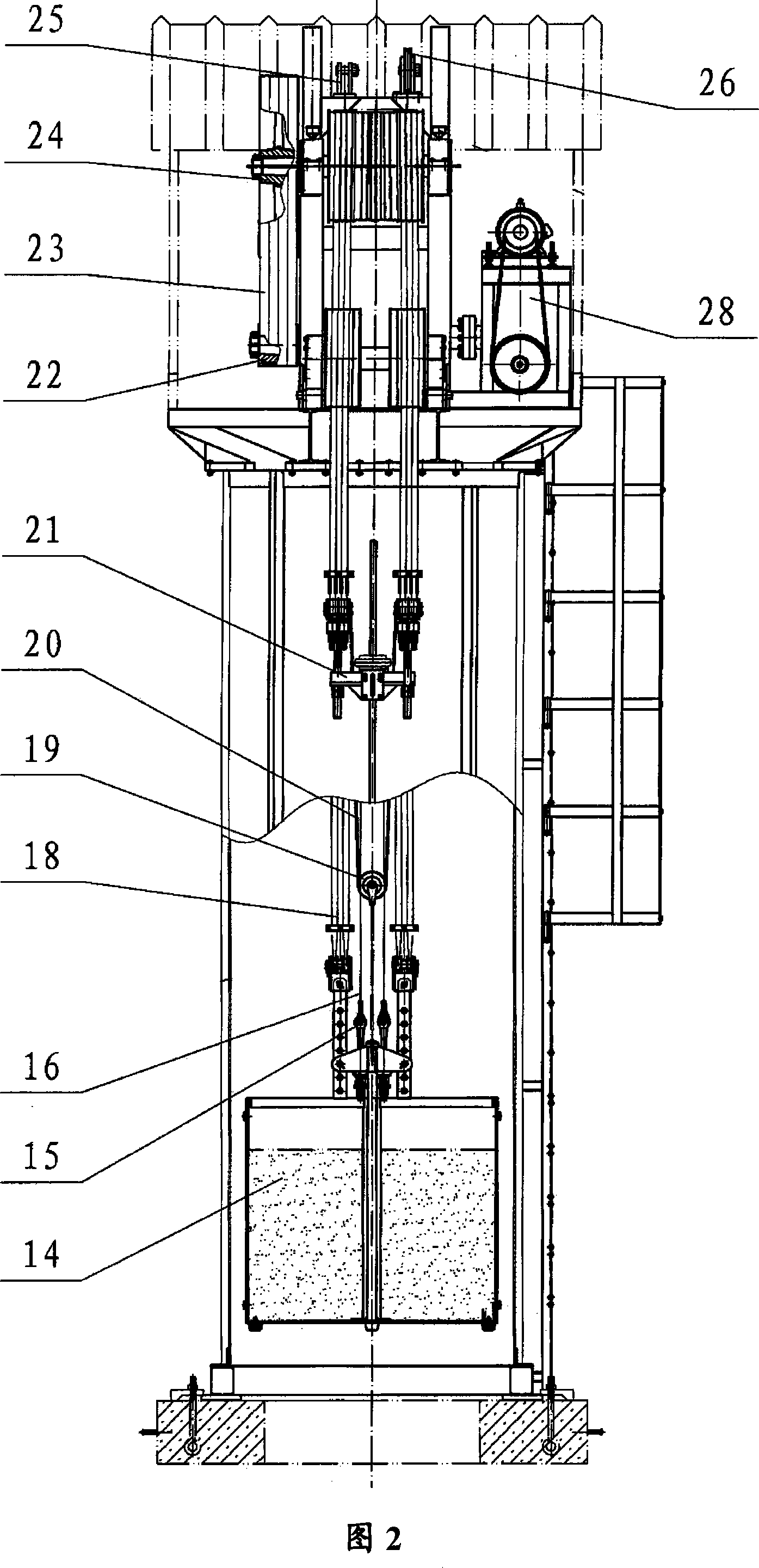
[0024] As shown in Figures 1, 2, and 3, in one embodiment of the present invention, a pumping unit is provided, which includes a main frame 1, a bracket 8, a motor 10, a brake 11, a control device 9, an oil pumping Bar 4, rope hanger 21, counterweight 14, drive shaft 30, drive rope 18, drive wheel 29, winch machine 28 and winch rope 20 and transmission device. Wherein, the top of the main frame 1 has a support 8, the support 8 has a platform, the drive shaft 30 is installed on the support 8, the drive wheel 29 is installed on the drive shaft 30, the sucker rod 4 and the rope hanger 21 is connected with counterweight 14 by drive rope 18 that goes around drive wheel 29.

[0025] In the invention, the control device can be in the form of an electric control cabinet 9, in which electrical comp...


PUM


Abstract

The pumping unit includes a main frame, a support on the frame, a motor mounted on one platform in the support, a brake mounted on the motor, a control device connected to the motor and the brake and outputting voltage in set frequency to the motor, a drive device connected between the motor output shaft and the drive shaft, a pumping rod, a polished rod eye, a balance weight, a driving shaft mounted on the support, a driving rope to connect the pumping rod and the polished rod eye to the balance weight, a driving wheel mounted on the driving shaft, a winch set on the support and connected to the balance weight, and a hoist rope. The present invention elevates the balance weight with the winch, rather than directly with the motor, and can lower the power of the motor obviously.

Description

technical field [0001] The invention relates to an oil production device, in particular to an oil pumping unit. Background technique [0002] In the current oil pumping machines, some pumping units work in a symmetrical balance mode between the counterweight and the pumping mechanism. When installing or maintaining this type of pumping unit, it is usually necessary to lift the counterweight to a higher position. [0003] The patent application "oil pumping and workover rig" with the application number of 200410011020.5 discloses an oil pumping machine, which includes a main frame, an electric control cabinet, a counterweight, a rope suspension, a polished oil rod, a motor, a small Gears, large gears, sky wheels and gearboxes and other components. The motor transmits the torque to the sky wheel through the reduction box, drives the sky wheel to rotate, and then completes the up and down reciprocating motion of the sucker rod. Among them, one end of the sucker rod rope is co...

Claims


Application Information

Patent Timeline
Patent Type & Authority Applications(China)
IPC IPC(8): E21B43/00F16H37/12
Inventor 金成群
Owner WUXI DEPULAI GASOLINEEUM MACHINERY
Learn More