
Annular concentrically twisted bead cord

A bead, annular technology, applied in the direction of the bead, tire parts, reinforcement layers of pneumatic tires, etc., can solve the problem of the impracticality of the annular core, achieve weight and low cost, easy to remove burrs, weldability and heat resistance high sex effect

Active Publication Date: 2007-09-19
SUMITOMO ELECTRIC IND LTD +1
View PDF2 Cites 10 Cited by
  • Summary
  • Abstract
  • Description
  • Claims
  • Application Information

AI Technical Summary

Problems solved by technology

Thus, such toroidal cores are practically impractical

Method used


Image

  • Annular concentrically twisted bead cord
  • Annular concentrically twisted bead cord
  • Annular concentrically twisted bead cord

Examples


Embodiment Construction

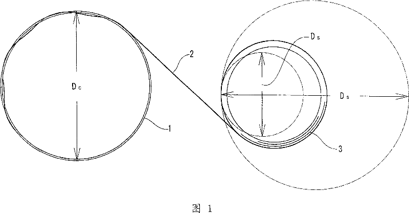
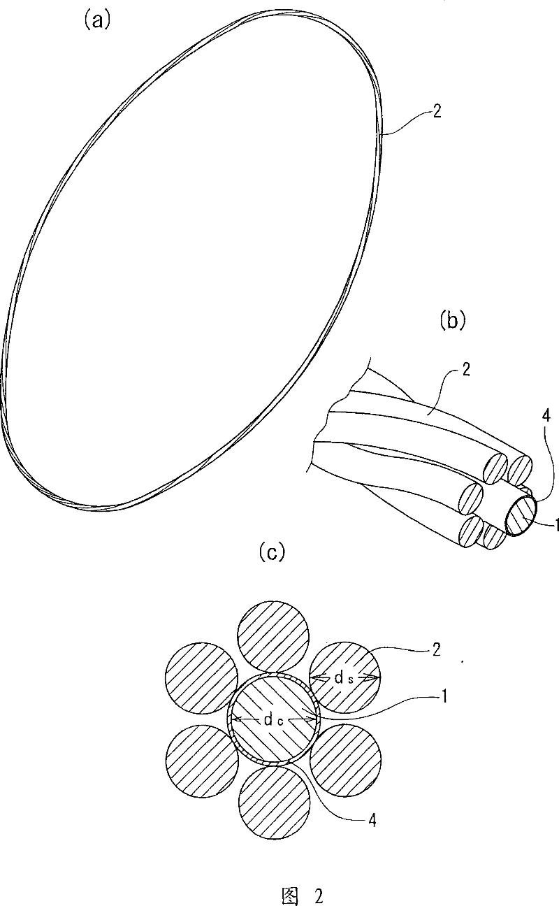
[0049] The embodiments of the present invention will now be described with reference to the drawings. As shown in Figures 1 and 2(a)-2(c), the annular concentric bead cord of this embodiment has a wire coil diameter of D C The diameter of the annular core 1 and the wire coil is D S The covered wire 2 is supplied from the covered wire supply tray 3 and spirally wound on the annular core 1. In this embodiment, as shown in Figures 2(b) and 2(c), the diameter is d S The covered wire 2 is wound with a diameter of d C A single sheath is formed by forming 6 circles along the ring core of the ring core. However, the covered wire can also be wound on the annular core to form multiple sheaths.

[0050] The two ends of the steel wire are welded together to form an annular core, where the diameter of the steel wire is slightly larger than the diameter of the covered wire 2 (proportion (d C / d S ) = 1.04 to 1.30) and made of medium carbon steel with a carbon content of 0.28 to 0.56 by weight. ...


PUM


Abstract

A bead cord which is lightweight and inexpensive, high in formability, and includes an annular core that is high in corrosion resistance. The bead cord which is lightweight and inexpensive and high in formability includes an annular core 1 and a wrap wire 2 helically wrapped around the annular core 1, the annular core 1 being made of a medium carbon steel or an alloy steel having a lower C content and containing specific elements in suitable amounts, and having a diameter d c that satisfies the following relation 1.04 <=d C / d S <= 1.30 with respect to the diameter ds of the wrap wire 2, the wrap wire 2 having a coil diameter D S which is 0.5 to 1.3 times the coil diameter D C of the annular core 1. In order to improve the corrosion resistance of the annular core 1, the annular core 1 may be formed with a plating layer of an Al-Zn alloy or a thick plating layer of Zn, or the annular core 1 may be made of stainless steel.

Description

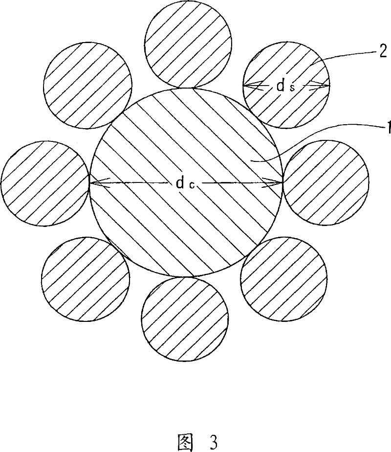
Technical field [0001] The present invention relates to a bead cord that is embedded in the bead of a pneumatic tire to strengthen the bead, and more particularly to an annular concentric bead cord, which has an annular core and is spirally wound on the annular core. A sheath or multiple sheaths formed. Background technique [0002] Annular concentric bead cords are widely used to reinforce the beads of various vehicle tires. As shown in Figure 3, many such cords are formed by spirally winding the covered wire 2 in a single layer or multiple layers on an annular core 1, wherein the annular core 1 is formed by abutting the two ends of the steel wire and welding them together. (As disclosed in Patent Document 1). The diameter of the covered wire 2 is smaller than the diameter of the annular core 1. [0003] The steel wire forming the toroidal core is typically a low carbon steel wire with a carbon content of 0.06 to 0.15 percent by weight. In order to ensure sufficient strength and...

Claims


Application Information

Patent Timeline
IPC IPC(8): B60C15/04B60C9/00C22C38/00C22C38/18C22C38/54D07B1/06
CPCD07B1/062D07B2205/306D07B2201/2013D07B2205/3092D07B2201/2051D07B2201/2065D07B2205/3071D07B2501/2053D07B2205/305D07B2201/2011D07B2201/2059D07B1/066D07B2801/12D07B2801/14D07B2801/18
Inventor 笹部博史若原仁志冈本贤一
Owner SUMITOMO ELECTRIC IND LTD
Learn More