
Double-safety regulating valve

A double safety and safety valve technology, applied in the direction of adjusting fuel supply, valve lift, valve details, etc., can solve the problems of high cost and large coil volume, and achieve the effect of simplifying the structure and reducing the total volume

Inactive Publication Date: 2007-09-12
G CARTIER TECH
View PDF1 Cites 3 Cited by
  • Summary
  • Abstract
  • Description
  • Claims
  • Application Information

AI Technical Summary

Problems solved by technology

This makes the coil bulkier and more expensive

Method used


Image

  • Double-safety regulating valve
  • Double-safety regulating valve
  • Double-safety regulating valve

Examples


Embodiment Construction

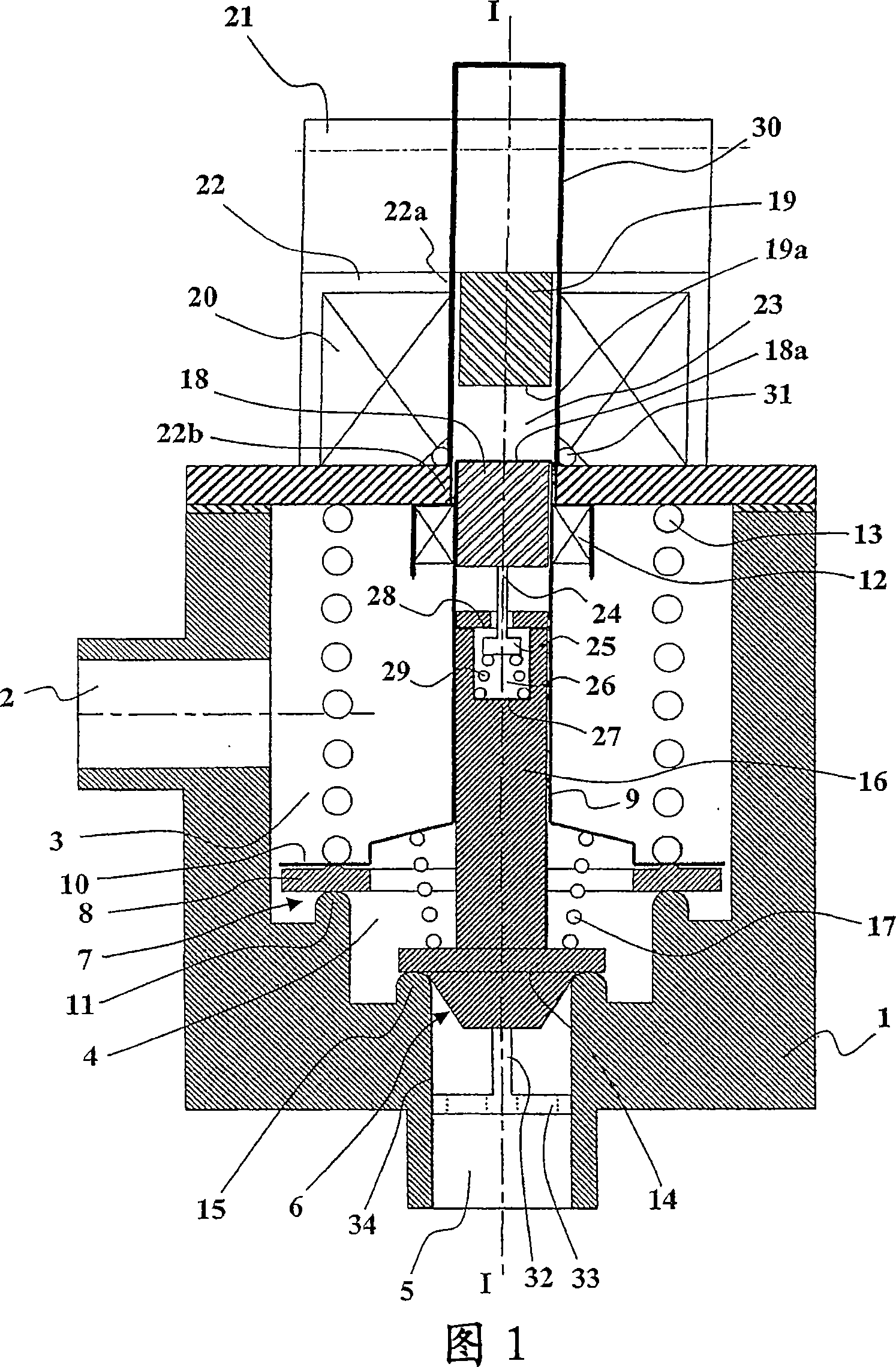
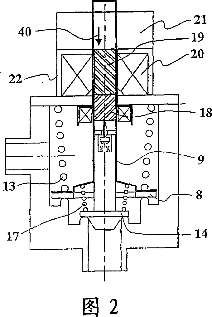
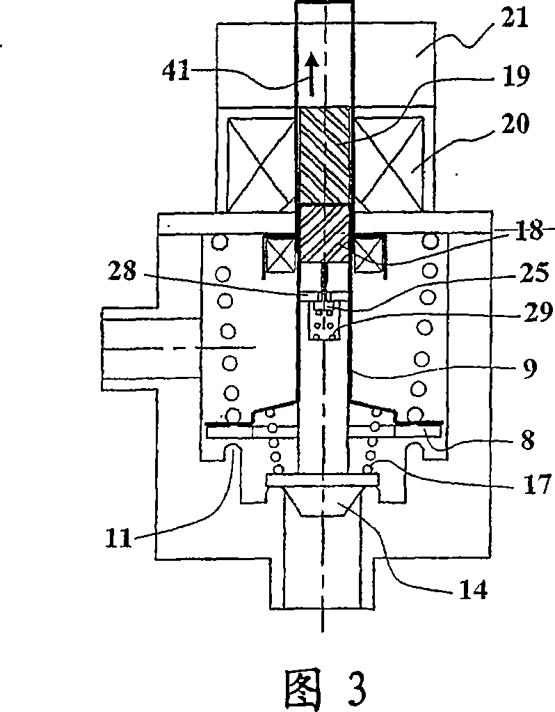
[0048]The dual safety fluid regulating device shown in FIG. 1 comprises a device body 1 in which a fluid passage having an inlet 2 , an upstream chamber 3 , an intermediate chamber 4 and an outlet 5 is provided.

[0049] The device body 1 is also provided with a regulating valve assembly 6 and a safety valve assembly 7, which are connected in series in the fluid passage and arranged one behind the other on a common axis I-I.

[0050] The safety valve assembly 7 comprises a safety valve 8 carried by a hollow axial drive shaft in the form of an axial blind pipe 9 . The open end of the axial blind pipe 9 is fastened on the safety valve 8 . For example, the open end of the axial dead-leg 9 comprises an annular radial lip 10 below which the safety valve 8 is compressed in a sealing manner facing the safety seat 11 and held by eg crimping (crimping). In particular, the edge of the annular radial lip 10 can be bent inwards and engages in an outer radial annular slot on the safety va...


PUM


Abstract

The invention concerns a device comprising a regulating valve (6) and a safety valve (7) connected in series in a fluid channel of the body of the device (1). A regulating valve (14) is driven by a mobile magnetic core (18) with a longitudinal displacement capacity by the sliding of an axial tube (24) in an axial housing (26) of an axial core (16) integral with the regulating valve (14). A safety valve (8) is connected to a blind axial tube (9) wherein slides the mobile magnetic core (18). The blind axial tube (9) slides in the tube of a field coil (20), and the mobile magnetic core (18) is located opposite a driving magnetic core (19) biased by a linear actuator (21). The powering of the field coil (20) couples the magnetic cores (18, 19) to move the valves through the linear actuator (21). The interruption of the power supply to the field coil (20) disconnects the magnetic cores (18, 19), and the valves (8, 14) are closed independently of each other under the action of return springs (13, 17).

Description

technical field [0001] The present invention relates to a dual safety fluid regulating electromagnetic device for continuous control of fluid flow in a fluid channel within the body of the device. Background technique [0002] Such a device can be used to regulate the flow of gas to a gas cooker or gas boiler. [0003] From document WO 02 / 070936 is known a double safety fluid regulating device comprising a regulating valve assembly and a safety valve assembly placed side by side, connected in series in a fluid channel and accommodated in a common device body. The safety valve assembly includes a safety coil magnetically connected to a movable safety core of the safety valve by a safety magnetic circuit bias. Energizing the safety coil causes the safety valve to fully open. De-energizing the safety coil causes the safety valve to return to the fully closed state under the action of the safety closing spring. The regulator valve assembly includes a regulator valve biased to...

Claims


Application Information

Patent Timeline
IPC IPC(8): F16K31/04
CPCF23N2035/14F23N2035/24F23N2035/16F16K1/443F16K31/082F23N1/005F23N2235/16F23N2235/24F23N2235/14
Inventor A·布尚考克M·肖蒙泰
Owner G CARTIER TECH
Learn More