
Device for filtering oil smoke

A technology of oil fume filtration and filter plate, which is applied in the direction of oil fume removal, household heating, heating methods, etc., which can solve the problems of high cost of use, reduction of comprehensive performance of oil fume, and large air volume loss of oil fume filter devices, so as to ensure long-term normal use , Improve the performance of range fume and prolong the maintenance-free time

Active Publication Date: 2007-09-12
NINGBO FOTILE KITCHEN WARE CO LTD
View PDF14 Cites 46 Cited by
  • Summary
  • Abstract
  • Description
  • Claims
  • Application Information

AI Technical Summary

Problems solved by technology

However, since the pore diameter of the mesh is always much larger than the diameter of the oil droplets mixed in the oil fume, the ability to filter oil fume is limited, and the smaller the mesh, the easier it is for oil to accumulate around the mesh, causing the mesh to shrink or even be blocked. Seriously affect the air intake of the range hood, thus affecting the overall fume removal effect of the range hood
More importantly, these filters are difficult to clean after they are stuck with greasy dirt, which makes users not very troubled, so usually they can only be replaced after a period of use, resulting in high cost of use
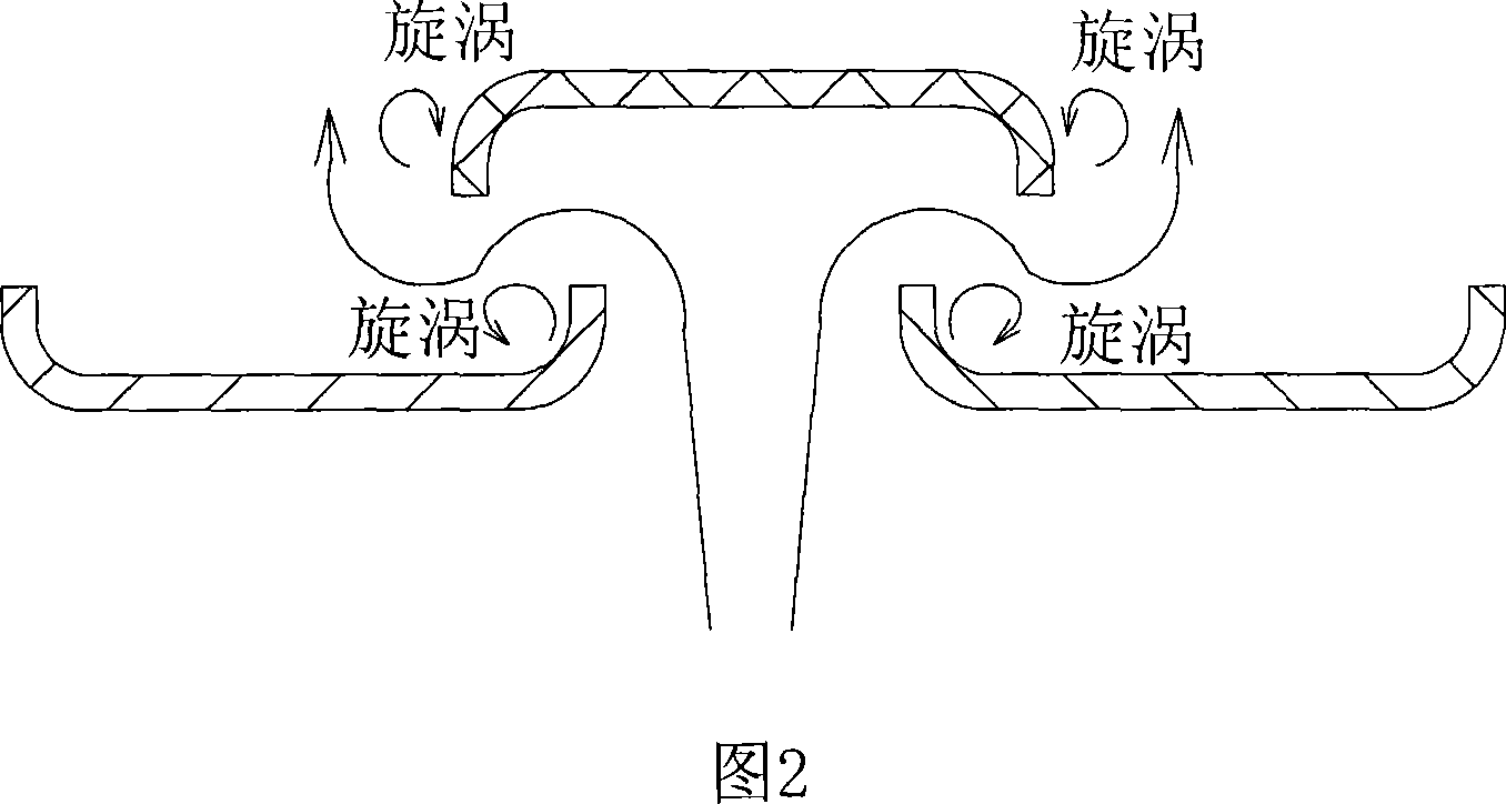
[0004] The second type is a single-layer orifice filter device. The orifice is a flat plate, that is, the edge of the hole is flush with the plate surface where it is located. As shown in Figure 1, there are long waist holes on the flat plate. When wind) enters the long waist hole, a large number of vortices will be generated on both sides of the hole, and the vortex will increase the noise
However, due to the influence of the shape of the second layer of filter plates that are relatively misplaced, the number of turns makes the air path tortuous, and because the upper panel is reversed, the airflow after the turn actually encounters a flat hole, so here (turning) The vortex is generated at the edge of the hole at the rear plate hole). Only by increasing the gap between the two filter plates can the vortex be reduced, but it cannot be completely solved (only the effect is reduced).
Because the fume gas must pass through the airflow channel of the double-layer filter plate, the tortuous channel and the flat plate hole after the turn (generating vortex) have double obstacles, so that the air volume loss of the oil fume filter device with this structure is large, even if the two-layer filter plate is enlarged The distance between the two layers is 2mm-10mm, and the air volume is still 3-5m lower than that of the single-layer plate filter. 3 / min, air volume loss up to 30%
However, due to the tortuous airflow channel, the relationship between the change of direction of the airflow at the corner and the vortex, although the air volume loss of this oil fume filter device is large, the filtering effect of the oil fume gas entering the range hood is relatively good. The suction volume of oil fume gas (too much reduction in air volume) is reduced, which greatly reduces the comprehensive performance of the range hood.

Method used


Image

  • Device for filtering oil smoke
  • Device for filtering oil smoke
  • Device for filtering oil smoke

Examples


Embodiment 1

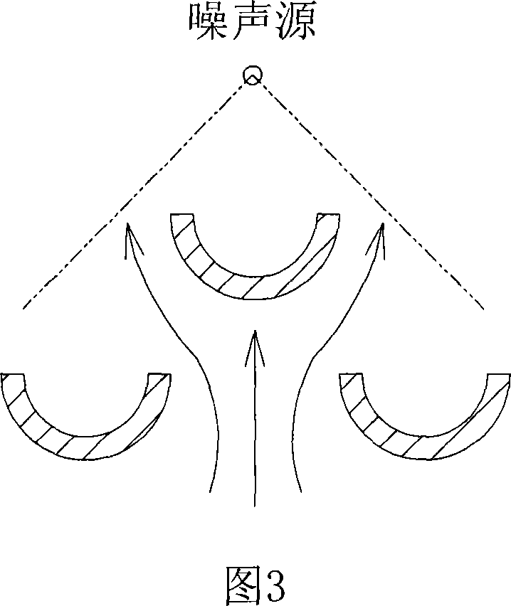
[0048] As shown in Fig. 3 to Fig. 7, it is a preferred embodiment of the present invention. As shown in Figures 3 to 7, the oil fume filtering device of this embodiment is in the shape of a rectangular funnel as a whole, and each side is a double-layer structure composed of two layers of planar filter plates 1, and thus makes the filter plate 1 relatively horizontal. The inclined arrangement means that the plate walls 3 between adjacent ventilation holes 2 on the filter plate 1 are arranged inclined.

[0049] The filter plate 1 is provided with strip-shaped ventilation holes 2 , and the width and spacing of the ventilation holes 2 on the two filter plates 1 are equal, and the ventilation holes 2 on the two filter plates 1 are arranged in dislocation. Flanges 31 are formed around the ventilation holes 1, and the directions of the flanges 31 of the ventilation holes 2 on all the filter plates 1 are all facing the inside of the range hood.

[0050] The cross-sectional shape of t...

Embodiment 2

[0056] As shown in FIG. 8 , with reference to FIGS. 4 to 6 , it is another preferred embodiment of the present invention. As shown in Figure 8, the oil fume filter device of this embodiment is basically the same as the oil fume filter device in Embodiment 1, the only difference is that the shape and relative size of the plate wall 3 between the adjacent ventilation holes 2 on the filter plate 1 are different. Specifically: in the present embodiment, the cross section of the plate wall 3 between the adjacent ventilation holes 2 on the filter plate 1 is a straight line segment and arc-shaped flanging 31 is extended at the two ends of the straight line segment. The width of the ventilation hole 2 is 10mm, and the ventilation The height H of the flanging 31 of the hole 2 is 5 mm, and the gap M between the two layers of filter plates 1 is 4 mm; in the two layers of filter plates 1, the width ratio of the wall 3 between the adjacent ventilation holes 2 on the upper filter plate 1 is ...

Embodiment 3

[0059] As shown in FIG. 9 , and referring to FIG. 4 to FIG. 6 , it is another preferred embodiment of the present invention. As shown in Figure 8, the oil fume filter device of this embodiment is basically the same as the oil fume filter device in Embodiment 1, the only difference is that the shape and relative size of the plate wall 3 between the adjacent ventilation holes 2 on the filter plate 1 are different. And the width and spacing of the ventilation holes 2 on the two layers of filter plates are different. Specifically: the cross-section of the wall 3 between adjacent ventilation holes 2 on the filter plate 1 in this embodiment is a straight line segment and arc-shaped flanging 31 extends at both ends of the straight line segment, and the upper layer filter plate 1 The upper layer of the ventilation hole 2 The width is 1mm, the height H of the flange 31 of the ventilation hole 2 1 is 2mm, the width of the ventilation hole 2 on the lower filter plate 1 is 8mm, and the h...


PUM


Abstract

This invention discloses an oil and smoke filtering device which includes at least two filtering pans that set vent holes. The holes on the border filtering pans set alternatively. Its character is in that the around of the vent holes has turned-over edge which faces the inside of the ventilator. It has such merits as good filtering effect, low wind loss, low noise, long non-maintain time which especially fits to the oil and smoke ventilator.

Description

technical field [0001] The invention relates to an oil fume filtering device for a range hood. Background technique [0002] At present, there are four main types of oil fume filtering devices installed at the air inlet of the range hood: [0003] The first is to use one or more layers of dense filter screens made of filaments to complete the filtration through micropores. However, since the pore diameter of the mesh is always much larger than the diameter of the oil droplets mixed in the oil fume, the ability to filter oil fume is limited, and the smaller the mesh, the easier it is for oil to accumulate around the mesh, causing the mesh to shrink or even be blocked. Seriously affect the air intake of the range hood, thereby affecting the overall fume removal effect of the range hood. What's more, these filter screens are difficult to clean after they are stuck with greasy dirt, which makes users not very troubled, so they usually have to be replaced after a period of use,...

Claims


Application Information

Patent Timeline
IPC IPC(8): F24C15/20
CPCB01D45/06F24C15/2035
Inventor 茅忠群
Owner NINGBO FOTILE KITCHEN WARE CO LTD
Learn More