
Hot-pipe solar cooker of optical lens

A technology for solar cookers and optical mirrors, applied in solar thermal devices, solar thermal energy, solar thermal power generation, etc., can solve the problems of inability to achieve high heat flux density thermal energy transfer, inability to achieve solar energy, etc.

Inactive Publication Date: 2007-09-05
CHENGDU AONENGPU TECH
View PDF0 Cites 21 Cited by
  • Summary
  • Abstract
  • Description
  • Claims
  • Application Information

AI Technical Summary

Problems solved by technology

[0004] With the development of optical mirror technology, ordinary optical mirrors or Fresnel optical mirrors can be used to collect solar energy, especially for the use of medium and high temperature solar energy. If the solar energy cannot be collected and focused, medium and high temperature solar energy cannot be realized. However, after the solar energy is collected by optical mirror technology, it will generate a high heat flux density, and the conversion of ordinary heat transfer materials will not be able to realize the transfer of heat energy with high heat flux density. Therefore, the combination of optical mirror technology and heat pipe The combination of technologies to utilize solar energy will enable the utilization of solar energy at medium and high temperatures

Method used


Image

  • Hot-pipe solar cooker of optical lens
  • Hot-pipe solar cooker of optical lens
  • Hot-pipe solar cooker of optical lens

Examples


Embodiment 1

[0053] Example 1: Manual solar cooker with disc heat pipe

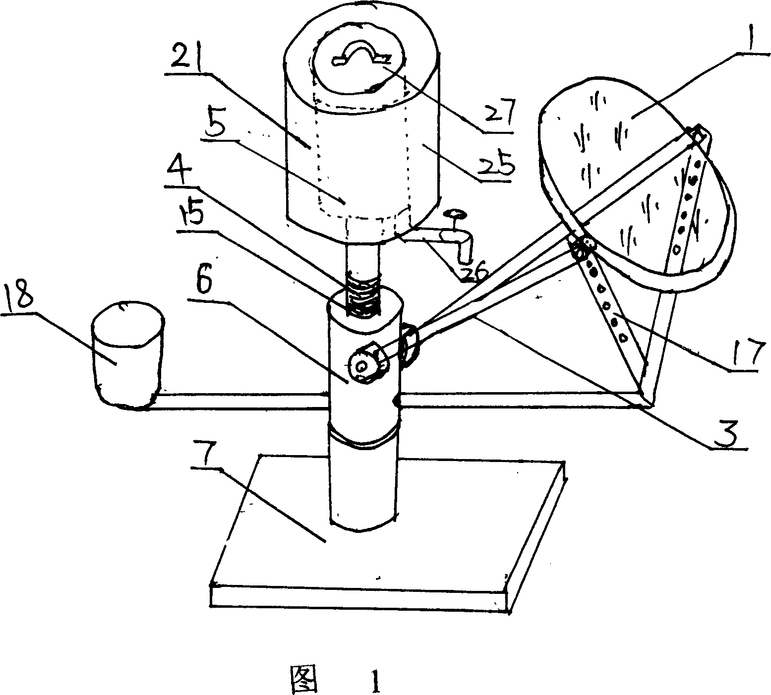
[0054] It is a 1.2-meter Fresnel lens (1) with a diameter of 1.2 meters. The evaporation end of the heat pipe solar cooker (21) is a heat pipe with a diameter of 38MM, and its condensation end is a groove of a concave shape (5). (25), a pipeline (26) connected to the outside is provided at its bottom, and a switch is provided on the pipeline so that the liquid flows out; this solar cooker adopts a manual tracking method, and the rotation axis (6) is rotated horizontally to adjust the series of holes ( 17) To adjust the height, the intermittent or simultaneous rotation axis uses a series of holes to track the sun. During the rotation of the optical mirror and the counterweight along the axis, the heat pipe solar cooker is stationary relative to the ground. This structure effectively realizes Tracking of solar energy;

Embodiment 2

[0055] Embodiment 2: The disc heat pipe automatically tracks the solar cooker

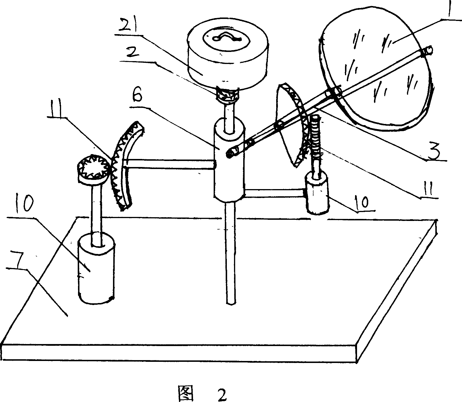
[0056] A disc-type solar cooker with an automatic tracking system, the solar cooker also adopts a heat pipe solar cooker structure, the same as in Embodiment 1, its tracking system adopts an arc-shaped gear processed on the horizontal rotating shaft (6), and uses the motor (10) to As the driving force, it is connected by a worm gear structure to realize the driving of the horizontal axis. An arc-shaped gear is installed on the optical mirror bracket, which is also connected by a worm gear structure to realize the drive in the height direction. The electrode is fixed on the shaft (6). and rotate simultaneously with the axis;

Embodiment 3

[0057] Embodiment 3: Table type cross semi-automatic tracking solar cooker

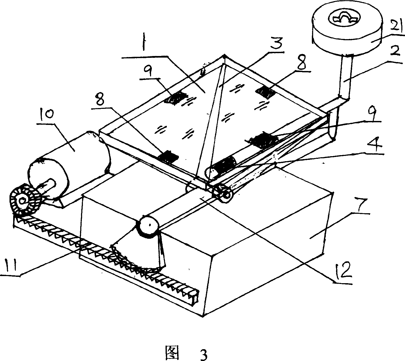
[0058] The table-type cross semi-automatically tracks the solar cooker, the structure of which is the same as the first embodiment, the optical mirror adopts a quadrilateral Fresnel lens 3, which is fixed on a mutually perpendicular axis 12 to form a funnel structure, and the solar cooker The evaporation end of the heat pipe is set at the crossing area of ​​the two axes, and the heat utilization material is arranged at the evaporation end 4, and four sensors are arranged on the lens, and there are two sensors in the X direction and the Y direction respectively. The value of the sensor is used to adjust the lens, and the gear mechanism 11 is used to adjust and control the axis in the X direction. The motor is used as the driving part, and the Y direction is manually tracked. The overall system is installed on a table, so it is called Cross semi-automatic solar cooker tracking system;


PUM


Abstract

The invention discloses a kind of heat pipe solar energy pipe, which use optical lens like lens or reflector to generate heat energy of high temperature. Use heat tube technology to absorb, transfer, and exchange heat. Use tray-type tracing system or cross-tracing system to collect solar energy and heat tube or forced convection circulation to realize heat exchange. Meanwhile, more than one tray-type or cross-type tracing systems can be adopted, which enables solar-energy usage in high temperature and high-power with high efficiency. Using heat accumulator to reserve heat energy provides practical technology to the usage of solar energy, especially the usage in the condition of high temperature.

Description

technical field [0001] The invention relates to thermal utilization of solar energy, including heating, hot water, cooking, power generation, cooling and drying, especially the medium and high temperature utilization of solar energy. Background technique [0002] The application technology of solar energy has been mature, mainly in the hot water of solar energy, which is used after absorbing heat by vacuum glass tube technology. In this application, there are heat pipes inserted into the vacuum glass tube to transfer heat to the outside to obtain solar energy. technology, but this technology uses the heat pipe as a heat transfer component after the vacuum glass tube converts solar energy into heat energy, instead of using the heat pipe as a solar energy conversion component; Conversion and heat transfer components, but mainly use trough reflectors to collect solar energy, instead of using the principle of optical mirrors to collect and utilize solar energy. [0003] Existin...

Claims


Application Information

Patent Timeline
IPC IPC(8): F24J2/02F24J2/04F24J2/38F24S20/30F24S50/20
CPCY02B40/18Y02E10/44Y02E10/47
Inventor 李建民
Owner CHENGDU AONENGPU TECH
Learn More