Servo branch of optical disc drive comprising a switchable diaphragm and a device for beam deflection, and methods for measuring beam landing and spherical aberration

A beam deflection, beam technology, applied in the field of optical systems

Inactive Publication Date: 2007-08-29
KONINKLIJKE PHILIPS ELECTRONICS NV
View PDF0 Cites 1 Cited by
  • Summary
  • Abstract
  • Description
  • Claims
  • Application Information

AI Technical Summary

Problems solved by technology

Detection is often limited only to zero order and positive and negative first order
The problem with the known arrangement is that for each detector the associated driver and electronics must be added to the system, thus increasing the cost and the crash space available in the arrangement

Method used


Image

  • Servo branch of optical disc drive comprising a switchable diaphragm and a device for beam deflection, and methods for measuring beam landing and spherical aberration
  • Servo branch of optical disc drive comprising a switchable diaphragm and a device for beam deflection, and methods for measuring beam landing and spherical aberration
  • Servo branch of optical disc drive comprising a switchable diaphragm and a device for beam deflection, and methods for measuring beam landing and spherical aberration

Examples


Embodiment Construction

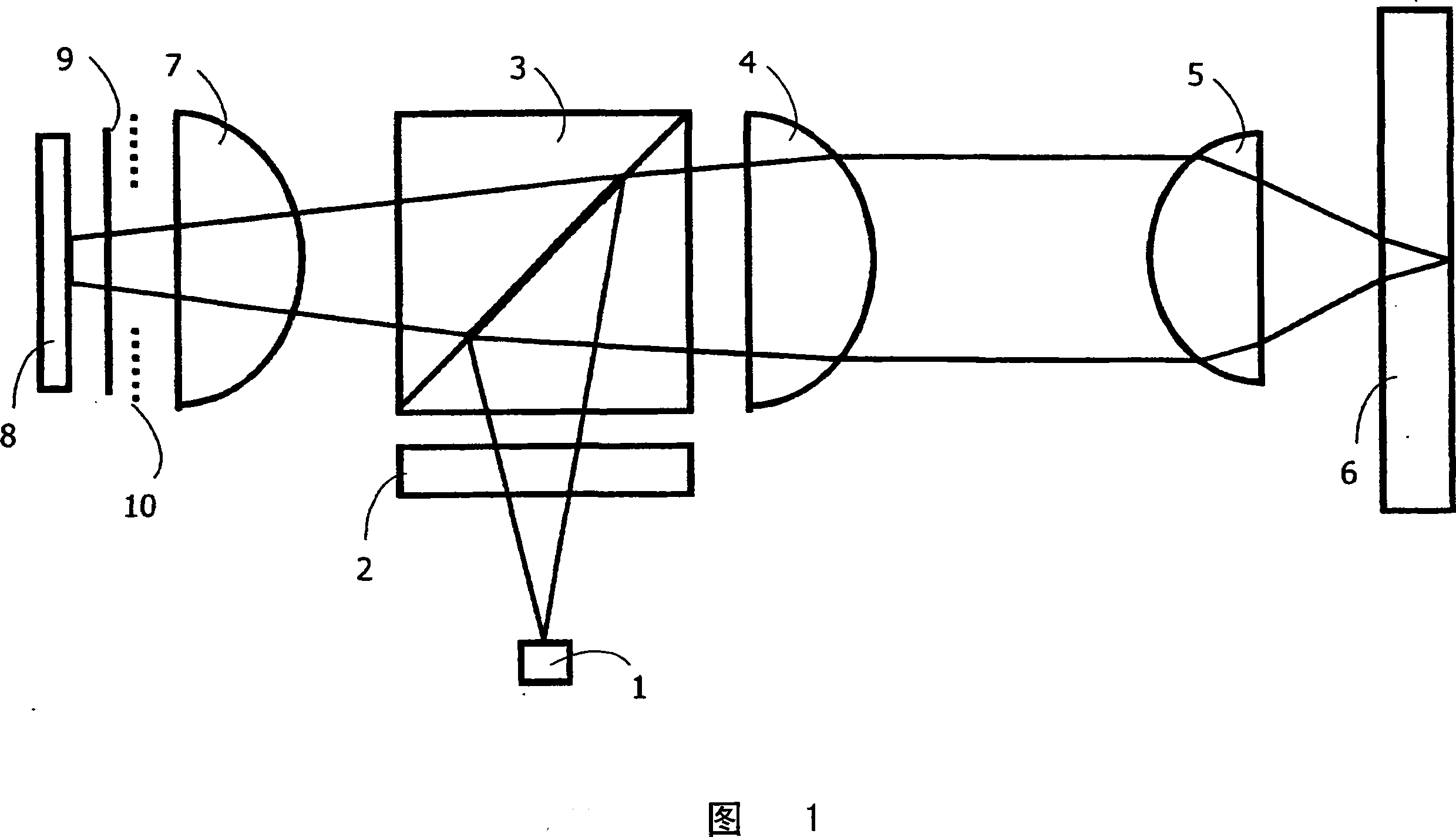
[0042] The embodiment of the invention shown in Figure 1 includes a number of elements:

[0043] Elements numbered 1 to 8 represent the optical path through the system in order from laser 1 to detector 8 . Elements 9 and 10 are additional elements according to the invention.

[0044]These elements act in combination so that the light from the laser 1 passes through the optics to the disk 6 and from there back to the detector 8 . At the beginning of the process, light from the laser diode 1 passes through the grating 2 and is diffracted into zero and higher order beams. Typically, only the zero order and the positive and negative first orders are considered, since these three beams provide the main spot for reading and writing to the disc 6 and can be used for beam landing or other measurements The two slave spots. A beam splitter 3 is added to the setup to direct the beam reflected from the disk 6 to a detector 8 . The laser diode 1 emits a divergent beam and therefore req...


PUM


Abstract

A switchable diaphragm (9) and a device for beam deflection (10) are placed in the servo branch of an optical drive, in a path of light beams of different diffraction orders. This permits redirection of light beam orders towards a detection means (8) on an individual basis and selection of light orders at a detection means (8) depending on requirements. The number of detectors in the device detection means (8) can thus be reduced, thereby also reducing additional components associated with those detectors and saving on cost and complexity. With such device functionality, new methods for measuring beam landing and spherical aberration are developed.

Description

technical field [0001] The subject-matter of the invention relates to the field of optical systems for information storage, and more specifically to the servo branch of an optical drive. Background technique [0002] The invention relates to an optically driven servo branch comprising detection means for detecting zero-order beams and higher-order beams. An example of such a device is known from "Encyclopaediaof Optical Engineering DOI: 10.1081 / E-EOE 120009664, 2003". [0003] The invention also relates to a method for measuring beam landing in such a device. [0004] The invention also relates to a method of measuring spherical aberration occurring in a light beam at a detector. [0005] Such devices typically include a plurality of individual detectors to detect the light beam passing along the servo optical path. A single beam is split into a plurality of diffraction orders between the light source and the starting point of the servo branch, so that the beam is split i...

Claims


Application Information

Patent Timeline
Patent Type & Authority Applications(China)
IPC IPC(8): G11B7/00G11B7/135
CPCG11B7/094G11B7/1353G11B7/13927G11B7/1381G11B7/0948G11B7/1369G11B7/09
Inventor S·斯塔林加B·H·W·亨德里克斯T·图克S·凯帕A·H·J·英明克C·T·H·F·利登鲍木
Owner KONINKLIJKE PHILIPS ELECTRONICS NV
Why Eureka
Try Eureka