Tyre turning mechanism

A technology of overturning mechanism and tires, which is applied in the direction of motor vehicles, conveyor objects, transportation and packaging, etc. It can solve the problems of inconvenient gripping by manipulators, and achieve the effect of compact structure and simple action

Inactive Publication Date: 2007-08-22
MIRACLE AUTOMATION ENG CO LTD
View PDF0 Cites 23 Cited by
  • Summary
  • Abstract
  • Description
  • Claims
  • Application Information

AI Technical Summary

Problems solved by technology

However, when the tire is transported on the roller table equipment, it is in a horizontal state, and it is very inconvenient for the workers to use the manipulator to pick it up.

Method used


Image

  • Tyre turning mechanism
  • Tyre turning mechanism
  • Tyre turning mechanism

Examples


Embodiment Construction

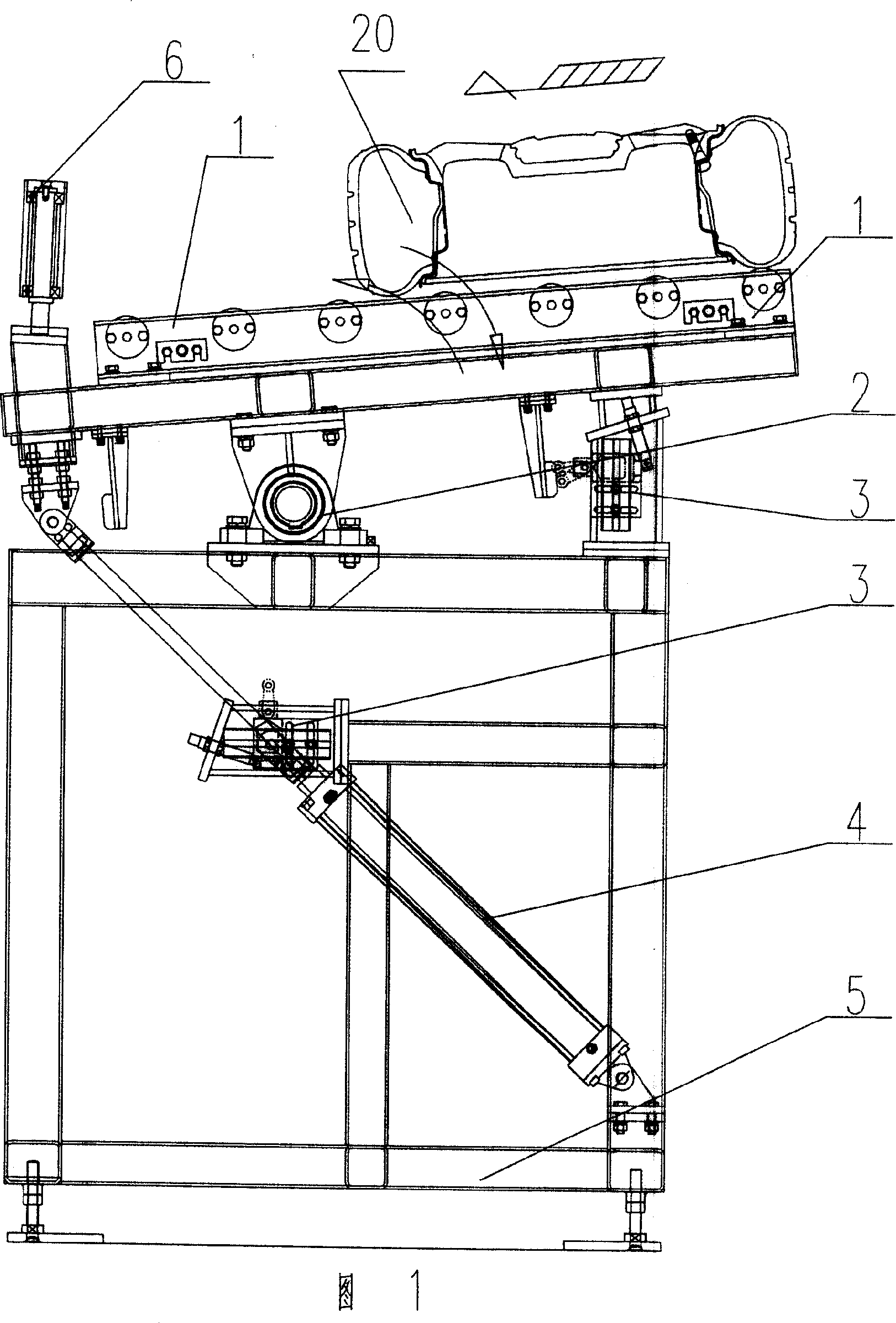
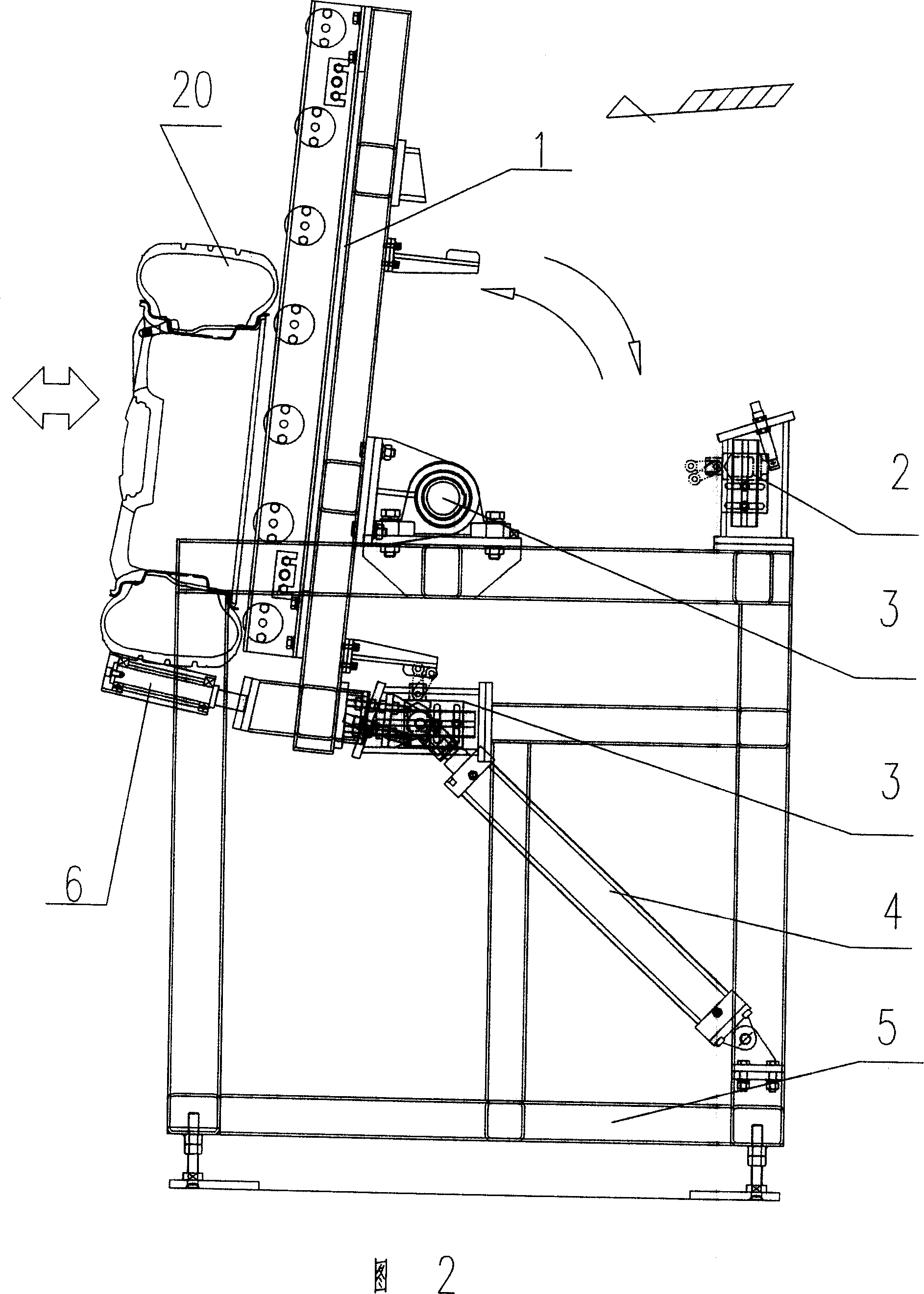
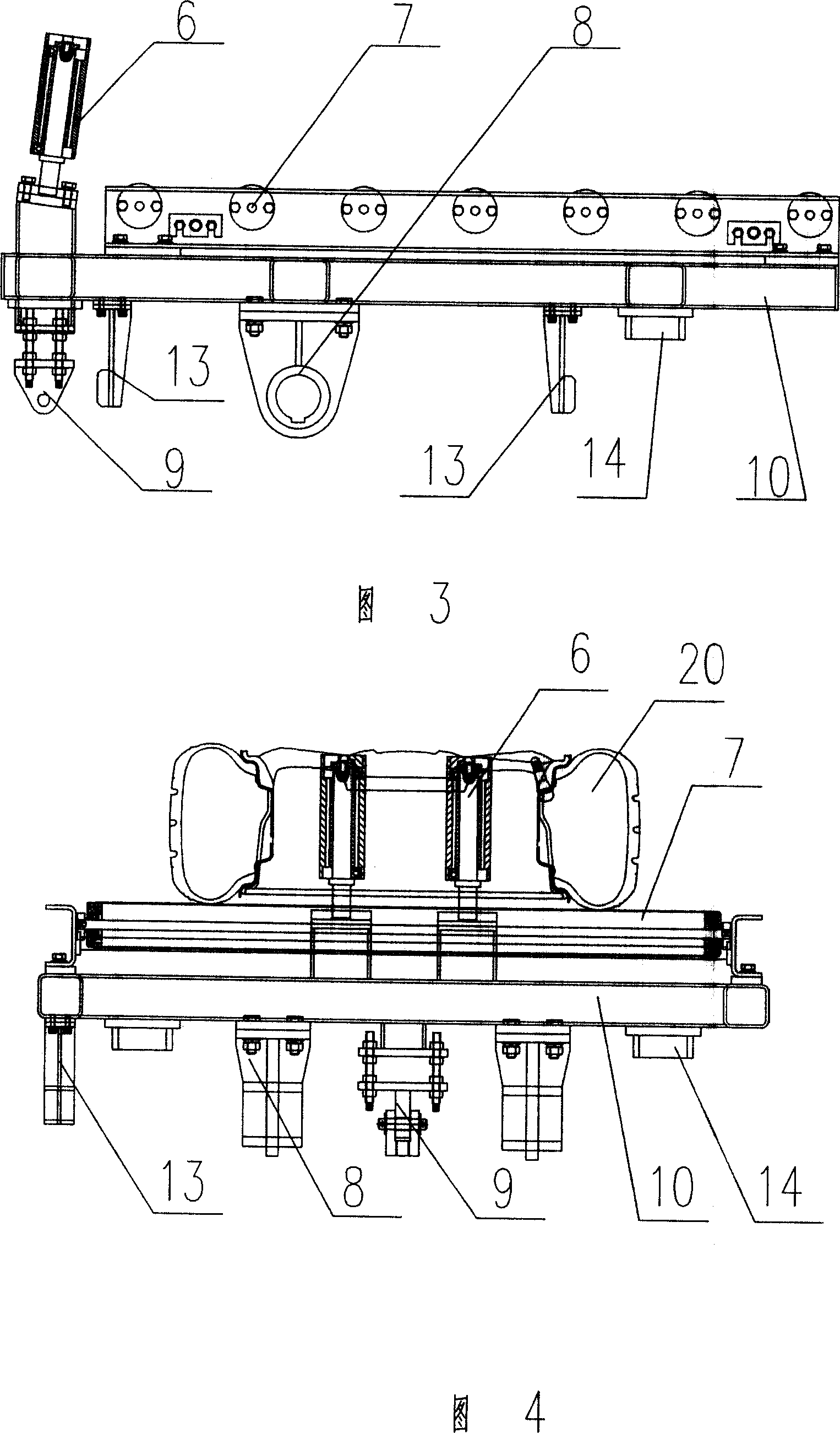
[0016] In the accompanying drawings, 1 is an overturn frame, 2 is a shaft seat, 3 is a detection limit device, 4 is a cylinder, 5 is a frame, 6 is a limit roller, 7 is a non-powered roller table, 8 is a rotating support, 9 Is the cylinder installation support, 10 is the installation frame, 11 is the bearing with seat, 12 is the shaft, 13 is the contact plate, 14 is the limit plate, 15 is the pneumatic buffer, 16 is the detection switch, 17 is the detection limit device Mounting seat, 18 is a support frame, and 19 is an adjustment foot.

[0017] As shown in the figure: the overturning frame 1 is hinged above the frame 5, and the cylinder 4 is hinged under the frame 5. The piston rod of the cylinder 4 is hinged with the front end of the overturning frame 1, and several Two roller tables 7 parallel to each other, a limit roller 6 is arranged on the front end of the reversing frame 1, and a detection limit device is set under the rear end of the reversing frame 1. During work, th...


PUM


Abstract

The present invention is one tyre turning mechanism, and belongs to the field of tyre assembling line machinery. The technological scheme of the present invention is that the tyre turning mechanism includes one turning rack hinged on the machine frame, one cylinder hinged below the machine frame, the piston rod of the cylinder hinged to the front end of the turning rack, parallel roller tracks homogeneously set on the turning rack, and limiting cylinder set in the front end on the turning rack. The tyre turning mechanism is used to turn tyre from horizontal state to vertical state for the manipulator to take conveniently in high work efficiency.

Description

technical field [0001] The invention belongs to a set of reloading machinery used on a tire conveying assembly line in an automobile assembly workshop. Background technique [0002] In the tire assembly area of ​​the automobile assembly workshop, in order to improve production efficiency, many large automobile manufacturers have added a set of tire roller conveyor equipment, which is responsible for sending tires from trucks or warehouses directly to the tire assembly area, and then using manipulators to take out and load the tires body system. However, the tire is in a horizontal state when it is transported on the roller table equipment, and it is extremely inconvenient for the worker to grip it with a manipulator. Contents of the invention [0003] The object of the present invention is to design a tire turning mechanism, which can turn the tire from a horizontal state to a vertical state, so that the manipulator can easily clamp the tire, thereby further improving wor...

Claims


Application Information

Patent Timeline
Patent Type & Authority Applications(China)
IPC IPC(8): B65G47/248B62D65/18
Inventor 杨雷李峰宝汪海燕
Owner MIRACLE AUTOMATION ENG CO LTD
Why Eureka
Try Eureka