
Six-rod whole hinge single-row drive type double pendulum angle milling head

A double swing angle milling head, driven technology, applied in the field of machine tools, can solve the problems of high stiffness, high load, low bearing capacity, etc., and achieve the effect of ensuring the range of motion, modular design, and easy manufacturing

Inactive Publication Date: 2007-08-08
SHANGHAI JIAO TONG UNIV
View PDF1 Cites 0 Cited by
  • Summary
  • Abstract
  • Description
  • Claims
  • Application Information

AI Technical Summary

Problems solved by technology

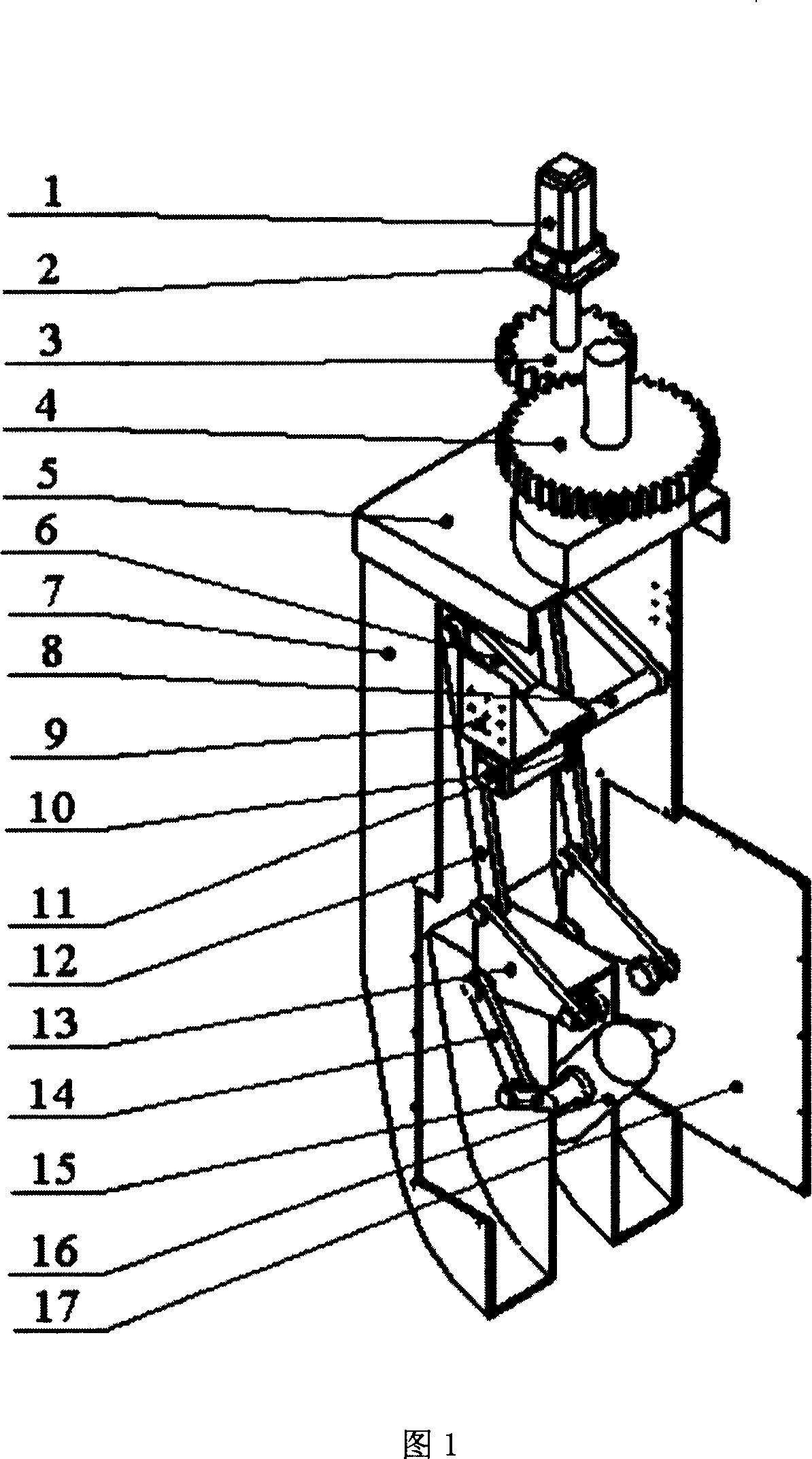
[0005] Aiming at the deficiencies of the prior art, the present invention provides a six-bar full-hinge single-row driven double-swing angle milling head, so that it can meet the working requirements of the double-swing milling head by adopting a new mechanism configuration of closed low-pair transmission, This configuration has the characteristics of high load, high rigidity, and large rotation angle. The rotation angle around the two axes can reach ±180° and greater than ±90° respectively, which meets or exceeds the international standard of similar products, and can solve the problem of the current double pendulum milling head due to high The auxiliary transmission has problems such as large volume, low rigidity, and low load-carrying capacity

Method used


Image

  • Six-rod whole hinge single-row drive type double pendulum angle milling head

Examples


Embodiment Construction

[0012] The embodiments of the present invention are described in detail below in conjunction with the accompanying drawings: the present embodiment is implemented on the premise of the technical solution of the present invention, and detailed implementation methods and processes are provided, but the protection scope of the present invention is not limited to the following implementations example.

[0013] As shown in Figure 1, this embodiment includes: a first controllable motor 1, a first coupling 2, a first cylindrical gear 3, a second cylindrical gear 4, a milling head cover plate 5, and a first pair of connecting rods 6. Milling head cover 7, transmission shaft 8, bracket 9, second controllable motor 10, second coupling 11, first pair of connecting rods 12, second pair of connecting rods 13, second pair of connecting rods 14, first Three pairs of connecting frame rods 15, milling head electric spindle 16 and a pair of milling head cover side cover plates 17.

[0014] Amo...


PUM


Abstract

The invention relates to a single bolt driving dual oscillating milling head. The No.1 controllable generator fixed with No.1 cylinder gear through No.1 coupler, No.2 cylinder gear fixed with the cover of the milling head cover, whose top cover and a pair of milling sleeve side cover fixed with the milling head sleeve, No.2 controllable generator installed on the bracket that fastened inside the milling head sleeve. Three pairs of linking brackets and two pairs of linkages set symmetrically at both sides of the electric main shaft of the milling head. The drive shaft fixes with the second controllable generator through the second coupler and fixed with the first pair of linking bracket. The first pair of linkage and the first pair of linking bracket or the second pair of linking bracket, the second pair of linkage and the second pair of linking bracket or the second pair of linkage and the third pair of linking bracket to form into rotating assistance respectively. The second and the third linking bracket connect to the milling head sleeve respectively, with the third linking bracket fixed with the main shaft of the milling head. It solves the issue of big size, low rigidity and poor bearing ability of the dual oscillating milling head.

Description

technical field [0001] The invention relates to a milling head in the technical field of machine tools, in particular to a six-bar full-hinge single-row drive type double-swing angle milling head, which is suitable for heavy-duty multi-axis numerical control high-precision high-speed machine tools. Background technique [0002] Double pendulum milling head is the core component of multi-axis control and five-axis linkage CNC machine tools. It mainly serves large and heavy CNC and ordinary milling and boring machine tools. The main engine is equipped with this kind of CNC milling head to control two-axis rotation to realize five-axis linkage to process complex The three-dimensional curved surface expands the processing range and use functions of the main machine, greatly improves the production efficiency and helps to ensure the processing accuracy. Because of its superiority, not only is the proportion of configuration when users order mainframes increased, but also the numb...

Claims


Application Information

Patent Timeline
IPC IPC(8): B23Q1/50
Inventor 高峰张青张勇郭为忠赵现朝刘仁强
Owner SHANGHAI JIAO TONG UNIV
Learn More