Improved clock pendulum driving device
A driving device and an improved technology are applied to the driving mechanism of clocks, mechanically driven clocks, clocks and other directions, which can solve the problems of large clockwork mechanism, cumbersome use and operation, inconvenient maintenance and repair, etc., and achieve easier maintenance and simplified transmission mechanism. , the effect of saving materials
- Summary
- Abstract
- Description
- Claims
- Application Information
AI Technical Summary
Problems solved by technology
Method used
Image

Examples
Embodiment 1
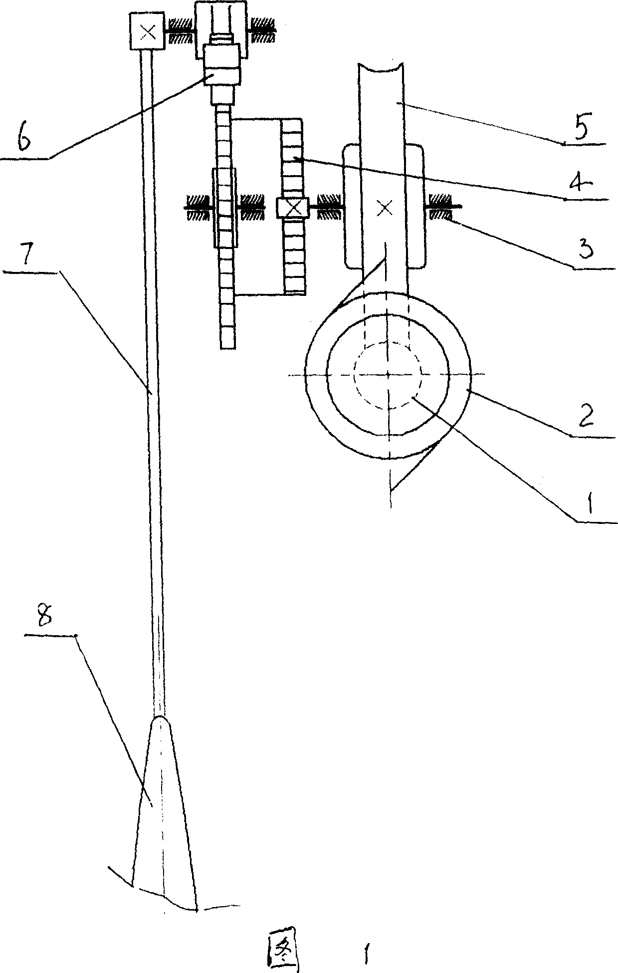
[0016] As shown in FIG. 1 , this embodiment includes a pendulum 8 , a pendulum mechanism 7 for driving the pendulum 8 to swing, and an escapement mechanism 6 for driving the pendulum mechanism 7 to work. A motor 2 is also provided, the output shaft of which is connected with the worm 1 , and the worm wheel 5 matched with the worm is connected with the escape wheel of the escapement mechanism 6 through the elastic assembly 4 .
[0017] The elastic assembly 4 is a clockwork or torsion spring; one end of the elastic assembly 4 is connected to the worm wheel 5 , and the other end is connected to the escape wheel shaft fixed to the escape wheel of the escapement mechanism 6 .
Embodiment 2
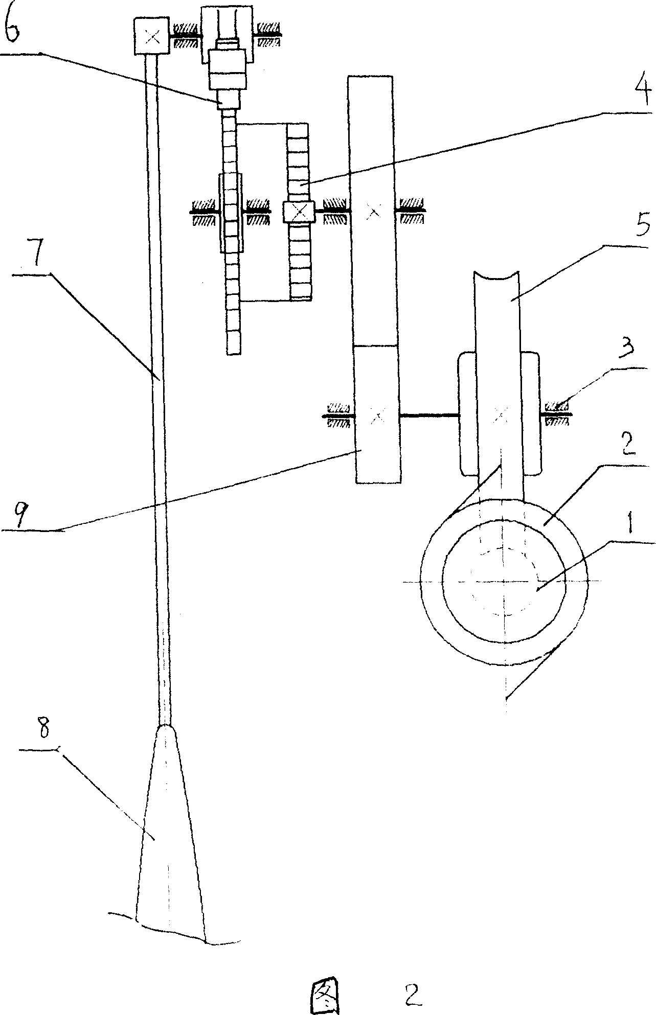
[0019] As shown in FIG. 2 , this embodiment includes a pendulum 8 , a pendulum mechanism 7 for driving the pendulum 8 to swing, and an escapement mechanism 6 for driving the pendulum mechanism 7 to work. A motor 2 and a gear transmission mechanism 9 are also provided, and the worm wheel 5 is connected with the escape wheel of the escapement mechanism 6 through the gear transmission mechanism 9 and the elastic assembly 4 in turn.
[0020] The elastic component 4 is a clockwork or torsion spring; one end of the elastic component 4 is connected to the driven gear of the gear transmission mechanism 9 , and the other end is connected to the escape wheel shaft fixed with the escape wheel of the escapement mechanism 6 .
Embodiment 3
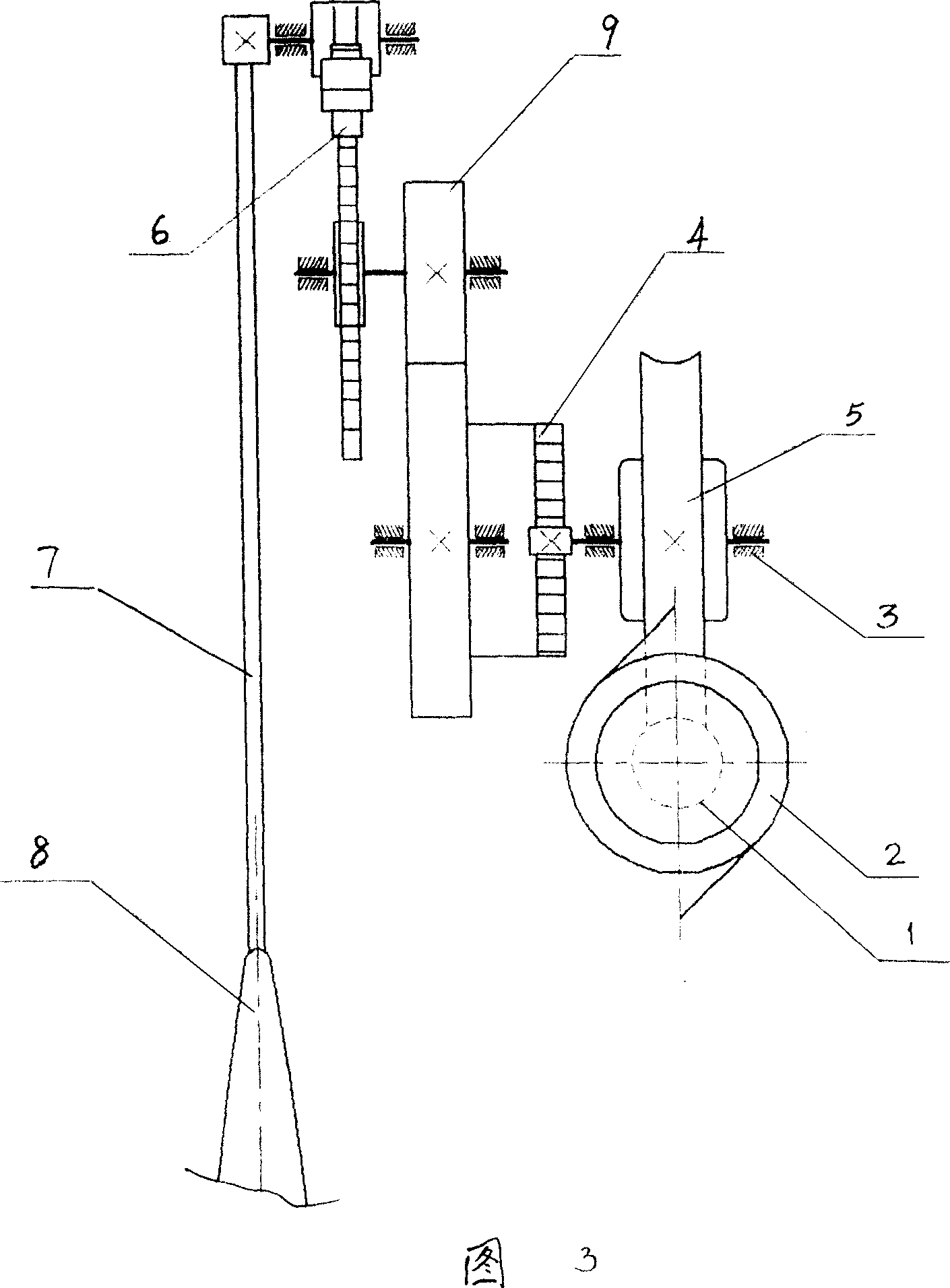
[0022] As shown in FIG. 3 , this embodiment includes a pendulum 8 , a pendulum mechanism 7 for driving the pendulum 8 to swing, and an escapement mechanism 6 for driving the pendulum mechanism 7 to work. A motor 2 and a gear transmission mechanism 9 are also provided, and the worm wheel 5 is connected with the escape wheel of the escapement mechanism 6 through the elastic assembly 4 and the gear transmission mechanism 9 in turn.
[0023] The elastic component 4 is a spring or torsion spring; one end of the elastic component 4 is connected to the worm wheel 5 , and the other end is connected to the driving gear shaft of the gear transmission mechanism 9 .
PUM
 Abstract
Description
Claims
Application Information
 - R&D
- Intellectual Property
- Life Sciences
- Materials
- Tech Scout
- Unparalleled Data Quality
- Higher Quality Content
- 60% Fewer Hallucinations
Browse by: Latest US Patents, China's latest patents, Technical Efficacy Thesaurus, Application Domain, Technology Topic, Popular Technical Reports.
© 2025 PatSnap. All rights reserved.Legal|Privacy policy|Modern Slavery Act Transparency Statement|Sitemap|About US| Contact US: help@patsnap.com