
Vehicle lighting device

A technology for vehicles and lamps, applied in the direction of headlights, road vehicles, vehicle parts, etc., can solve the problems of front vehicle glare, single high beam light distribution pattern, etc., and achieve the effect of improving safety, reducing glare and improving visibility.

Inactive Publication Date: 2007-08-01
KOITO MFG CO LTD
View PDF0 Cites 28 Cited by
  • Summary
  • Abstract
  • Description
  • Claims
  • Application Information

AI Technical Summary

Problems solved by technology

[0006] However, in conventional vehicle lamps, the high-beam light distribution pattern obtained from the high-beam irradiation light is single.
Therefore, there is a problem that it is difficult to form a very detailed suitable irradiation area according to various vehicle driving conditions
That is, when there are no pedestrians, vehicles in front of the vehicle ahead, and oncoming vehicles, by forming the high-beam light distribution pattern of the prior art, it is possible to ensure good long-distance visibility without causing glare. However, If there are pedestrians and oncoming vehicles, depending on the driving environment, it will cause a lot of glare to pedestrians and oncoming vehicles
In addition, when there is a vehicle in front, the high beam headlights are usually not turned on, but in this situation, there are also cases where it is desired to ensure the visibility of pedestrians on the shoulder side of the road.
In this case, if the high beam is turned on, it will cause glare to the vehicle in front

Method used


Image

  • Vehicle lighting device
  • Vehicle lighting device
  • Vehicle lighting device

Examples


Embodiment Construction

[0077] Embodiments of a vehicle lamp suitable for the present invention will be described below with reference to the drawings.

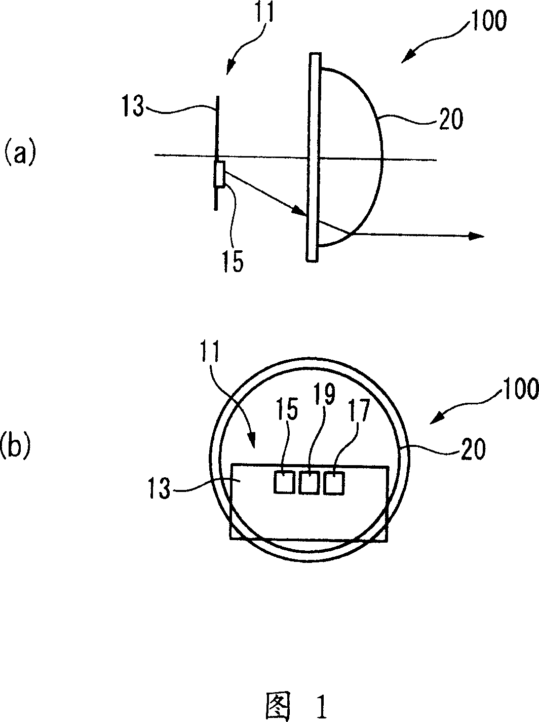
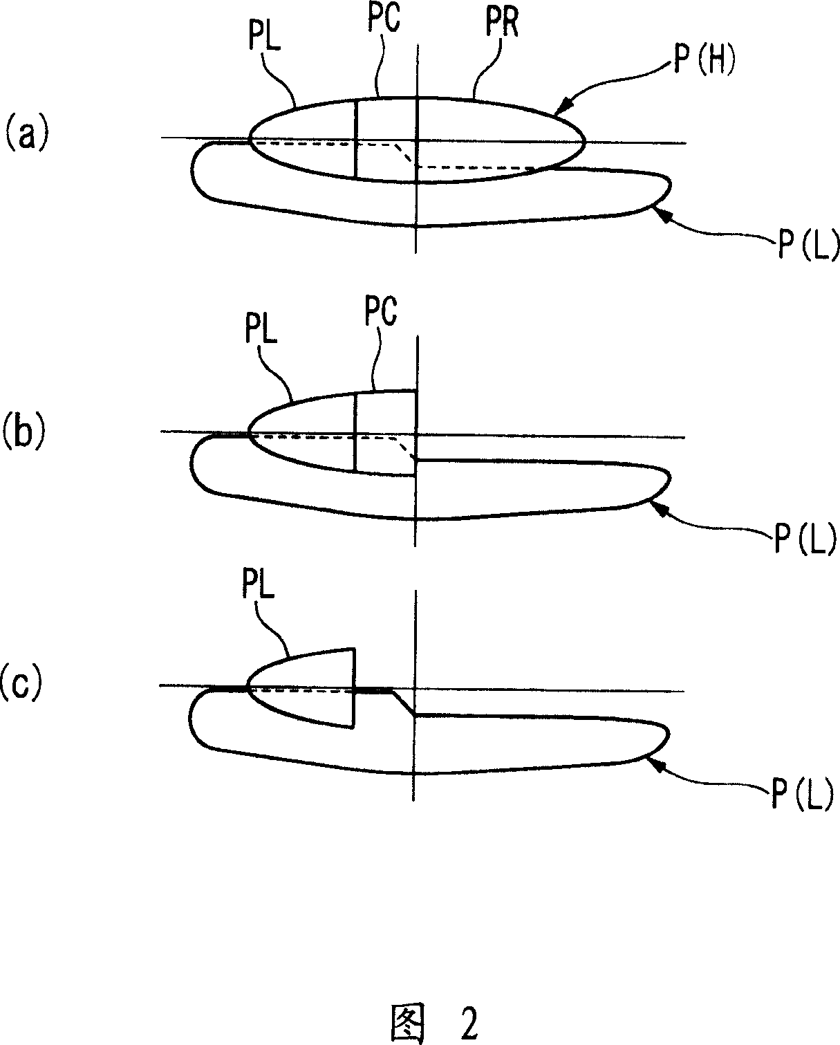
[0078] Fig. 1 is an explanatory diagram showing a vehicle lamp according to the present invention in a side view (a) and a front view (b). 2( a ), ( b ), and ( c ) are explanatory diagrams showing light distribution patterns formed by the vehicle lamp shown in FIG. 1 .

[0079] The vehicle lamp 100 includes a light source unit 11 for emitting light, and the light emitted from the light source unit 11 is directed forward to form a high-beam light distribution pattern P(H). The high-beam light distribution pattern P(H) has at least two or more illumination patterns that illuminate mutually different regions. In this embodiment, a case where there are three irradiation patterns PL, PC, and PR will be described as an example.

[0080] A control unit described later is connected to the light source unit 11, and the control unit can selectively perform ...


PUM


Abstract

A vehicle lighting device includes a light source unit for emitting light for forming a high beam light distribution pattern by projecting forward light from the light source unit. The high beam light distribution pattern has at least two illumination patterns which illuminate areas which are different from each other. A control unit is provided for controlling the at least two illumination patterns to be turned on and off selectively.

Description

technical field [0001] The present invention relates to a lamp for a vehicle that directs light from a light source unit forward to form a high-beam light distribution pattern. In particular, the present invention relates to a technology that improves visibility without causing glare to vehicles in front and oncoming vehicles. Background technique [0002] When the lamp unit included in the headlight of a vehicle lamp is a projection type, it includes a light source for emitting light, a reflector for reflecting the light emitted by the light source, a projection lens for projecting the light reflected by the reflector forward, and a projection lens. A holder for fixing the lens to the reflector, and a cover for shielding part of light projected from the reflector to the projection lens. In order to enhance the driver's visibility when driving at night, and not to dazzle the oncoming and front vehicles, it is best to adjust the headlights to high beam when there is no vehicl...

Claims


Application Information

Patent Timeline
Patent Type & Authority Applications(China)
IPC IPC(8): F21S8/10B60Q1/14F21V23/00H05B37/02F21W101/10F21Y101/02F21W107/10
CPCB60Q2300/112B60Q2300/056B60Q2300/42B60Q2300/45B60Q2300/41B60Q1/085F21S41/683F21S41/151
Inventor 小松元弘
Owner KOITO MFG CO LTD
Learn More