
Aeration device for polluted water purification processing and water scene, and its production method and usage method

A technology of sewage purification and aeration device, applied in water/sludge/sewage treatment, water aeration, chemical instruments and methods, etc. The design concept is scientific, the scope of use is expanded, and the debugging is simple and easy to implement

Inactive Publication Date: 2007-08-01
TIANJIN WATER RESOURCES RES INST
View PDF0 Cites 2 Cited by
  • Summary
  • Abstract
  • Description
  • Claims
  • Application Information

AI Technical Summary

Problems solved by technology

In the traditional aeration device, the method of reducing the aperture of the air outlet is generally used to generate smaller-diameter air bubbles. This kind of aerator has defects such as small air supply, easy blockage of the air outlet, and low efficiency.
[0003] The devices using the air flotation method have their own advantages, but they generally have the disadvantages of high energy consumption, complicated equipment, large floor space, and excessively large bubble diameters. Excessively large bubble diameters will cause many problems. Proportional to the square of the diameter of the bubble, the bubbles rise fast and the flocs are not easy to bond, and the flocs are not easy to rise to the water surface
In addition, all sewage purification devices cannot change the aeration method according to the change of water quality, and at the same time, the arrangement of aeration devices in water areas in cities will affect the urban landscape.

Method used


Image

  • Aeration device for polluted water purification processing and water scene, and its production method and usage method
  • Aeration device for polluted water purification processing and water scene, and its production method and usage method
  • Aeration device for polluted water purification processing and water scene, and its production method and usage method

Examples


Embodiment 1

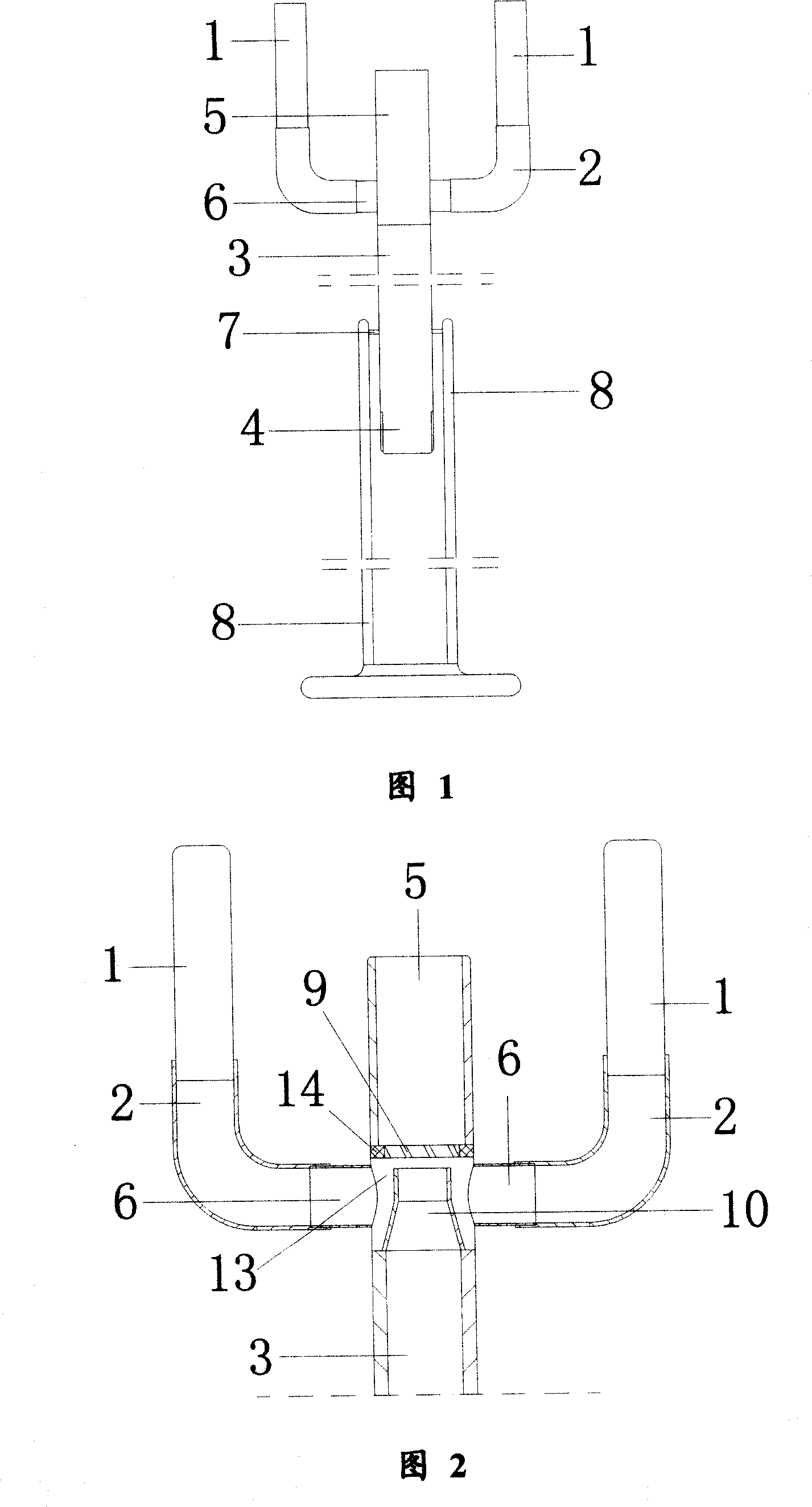
[0048] The water inlet pipe (3) is cylindrical, hollow in the pipe, and the top end of one end of the water inlet pipe (3) is connected smoothly with the other end of the air-water mixing nozzle (5). The pipes (5) are connected, the other end of the water inlet pipe (3) is the water inlet pipe port (4), the water inlet pipe port (4) is connected with the pipe (11), and the water body is delivered to the water inlet pipe (3) through (11) .

[0049] Two air supply pipes (6) are equidistantly arranged on the outside of one end of the water inlet pipe (3), and one end of the air supply pipe (6) is connected with the outside of one end of the water inlet pipe (3), and the air supply pipe (6) and the water inlet pipe (3) are connected with each other, and the air supply pipe (6) delivers air evenly to the water inlet pipe (3), as shown in Fig. 1 , Fig. 2 and Fig. 3 .

Embodiment 2

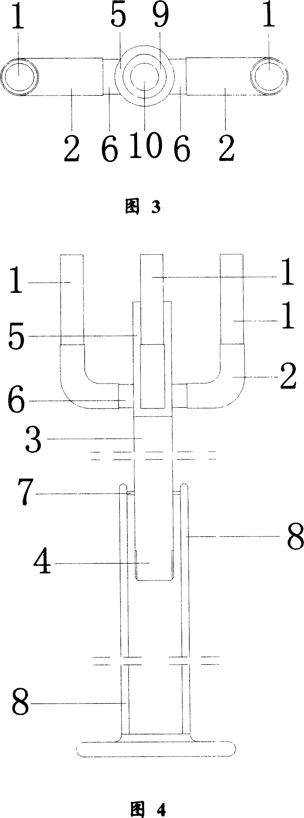
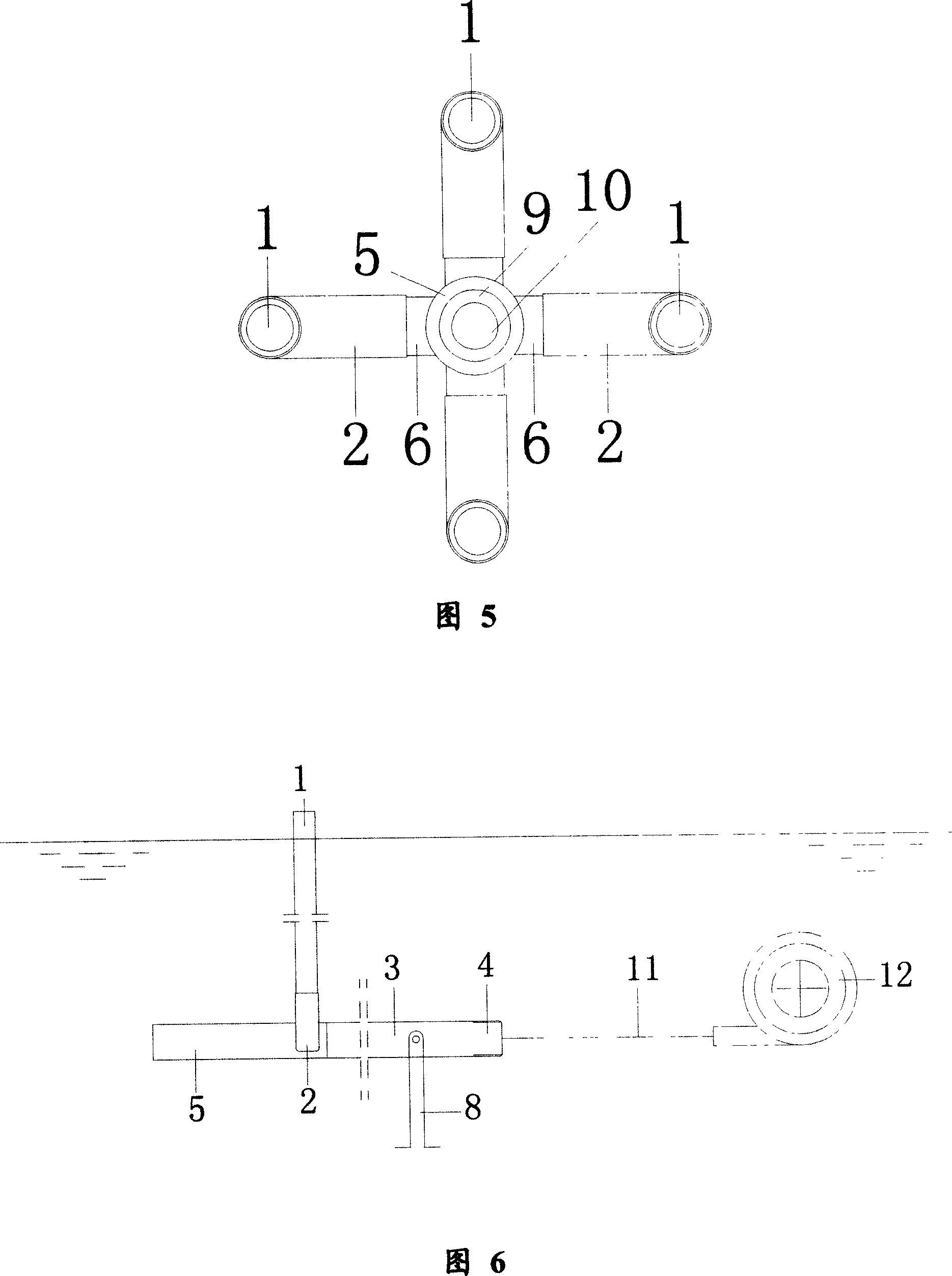
[0051] The water inlet pipe (3) is cylindrical, hollow in the pipe, and the top end of one end of the water inlet pipe (3) is connected smoothly with the other end of the air-water mixing nozzle (5). The pipes (5) are connected, the other end of the water inlet pipe (3) is the water inlet pipe port (4), the water inlet pipe port (4) is connected with the pipe (11), and the water body is delivered to the water inlet pipe (3) through (11) .

[0052] Four air supply pipes (6) are equidistantly arranged outside one end of the water inlet pipe (3), and one end of the air supply pipe (6) is connected with the outside of one end of the water inlet pipe (3), and the air supply pipe (6) is connected to the water inlet pipe. (3) are connected with each other, and the air supply pipe (6) evenly delivers air to the water inlet pipe (3), as shown in Fig. 2, Fig. 4 and Fig. 5 .

Embodiment 3

[0054] The other end of the air supply pipe (6) is movably connected with the other end of the swivel elbow (2), one end of the air supply pipe (6) is fixedly connected with the other end of the air induction pipe (1), and the swivel elbow (2) ) drives the air-inducing pipe (1) to rotate along the air-delivery pipe (6), and air is transported into the water inlet pipe (3) by the air-inducing pipe (1), the swivel elbow (2) and the air-delivery pipe (6).

[0055] A conical nozzle (10) is arranged in the pipe at one end of the water inlet pipe (3), and the inner wall of the nozzle (10) is smoothly connected with the inner wall of the water inlet pipe (3). speeds up the flow of water.

[0056] A negative pressure guide pressure ring (9) is arranged in the top end of one end of the water inlet pipe (3), and the negative pressure guide pressure ring (9) corresponds to the spray nozzle (10), and the negative pressure guide pressure ring (9) is Hollow cylindrical, the other end of th...


PUM


Abstract

The invention discloses a purifying device of effluent and making method and using method to aerate water, which is characterized by the following: the inlet pipe displays hollow cylinder shape; one end of inlet pipe connects the other end of composite sprayer glidingly, which transmits water to inlet pipe through pump pipe; the exterior of inlet pipe contains at least two transmitting pipes with equal distance, which transmits air to inlet pipe; the rotary table sprayer is set in the inlet pipe; the negative pressure guide pressurizing loop is set in the top of inlet pipe, which corresponds to sprayer; the sealed negative pressure composite gas-water bin is formed around sprayer; the rotary shaft is set on the exterior of inlet pipe, which connects rack.

Description

technical field [0001] The invention relates to a sewage purification treatment facility, in particular to an aeration and waterscape aeration device for sewage purification treatment, a manufacturing method and a using method. Background technique [0002] In sewage purification treatment, various aeration methods are mostly used to meet the amount of oxygen required in the metabolic process of aerobic microorganisms. Aeration devices are an important part of this sewage treatment method. In the traditional aeration device, the method of reducing the aperture of the air outlet is generally used to generate smaller-diameter air bubbles. This kind of aerator has defects such as small air supply, easy blockage of the air outlet, and low efficiency. [0003] The devices using the air flotation method have their own advantages, but they generally have the disadvantages of high energy consumption, complicated equipment, large floor space, and excessively large bubble diameters. E...

Claims


Application Information

Patent Timeline
IPC IPC(8): C02F3/02C02F7/00
CPCY02W10/10
Inventor 汪长余刘学功
Owner TIANJIN WATER RESOURCES RES INST
Learn More