
Angle-adjustable guide rail for cutting machine

An angle adjustment and cutting machine technology, which is applied in the field of guide rails, can solve the problems of affecting the normal use of guide rails, reducing cutting efficiency, wasting time, etc., and achieves the effects of novel design concepts, improved efficiency, and huge economic benefits

Active Publication Date: 2018-12-11
WUHU CHUANGYUAN NEW MATERIALS CO LTD
View PDF13 Cites 0 Cited by
  • Summary
  • Abstract
  • Description
  • Claims
  • Application Information

AI Technical Summary

Problems solved by technology

[0003] At present, when some cutting machines on the market are performing cutting work, the cutting machine will occasionally stop when the cutting machine is moving on the track, because some foreign objects will appear on the inner side of the guide rail as the cutting machine is used for a long time, and it is not easy to It is found that it is not easy to clean, which affects the normal use of the guide rail. Some cutting machines use rails to cut the cutting parts. When the cutting direction needs to be adjusted, the cutting parts need to be removed, adjusted and fixed again before cutting. , which will waste time and reduce the efficiency of cutting. Therefore, in view of the above problems, a guide rail for cutting machine that can be adjusted at an angle is proposed.

Method used


Image

  • Angle-adjustable guide rail for cutting machine
  • Angle-adjustable guide rail for cutting machine
  • Angle-adjustable guide rail for cutting machine

Examples


Embodiment Construction

[0018] The following will clearly and completely describe the technical solutions in the embodiments of the present invention with reference to the accompanying drawings in the embodiments of the present invention. Obviously, the described embodiments are only some, not all, embodiments of the present invention. Based on the embodiments of the present invention, all other embodiments obtained by persons of ordinary skill in the art without making creative efforts belong to the protection scope of the present invention.

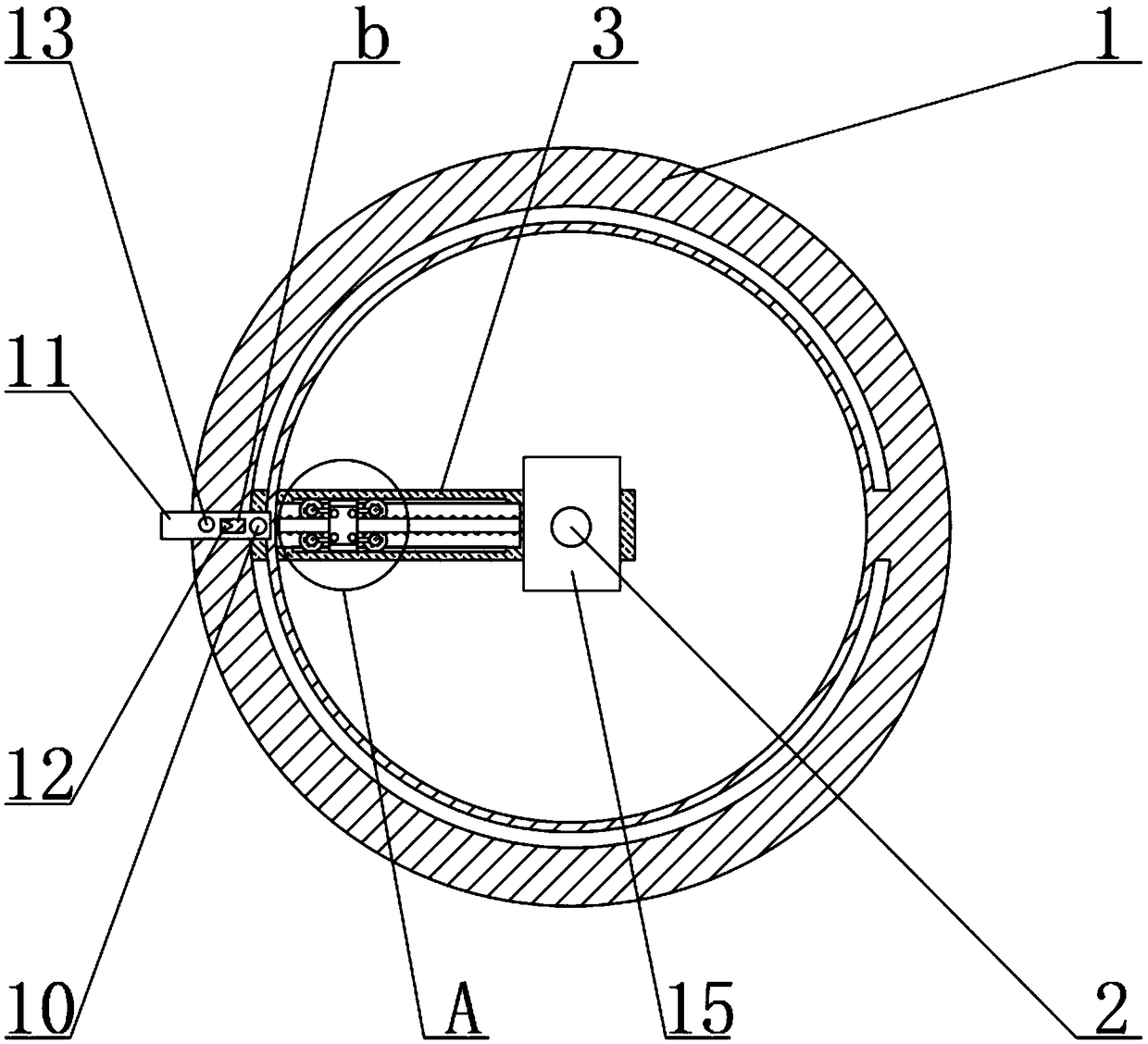
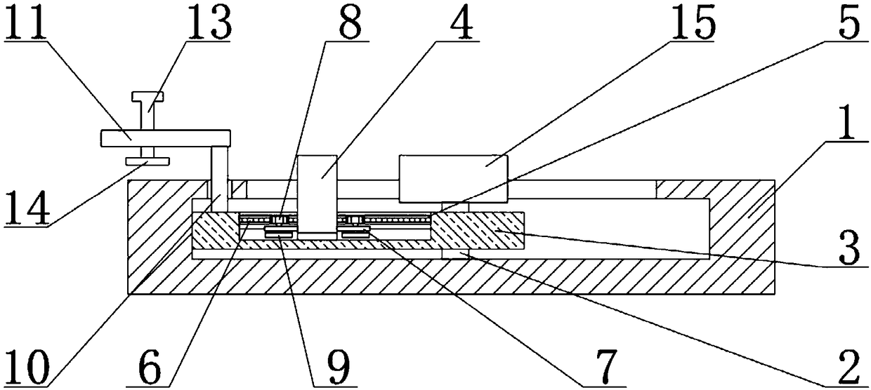
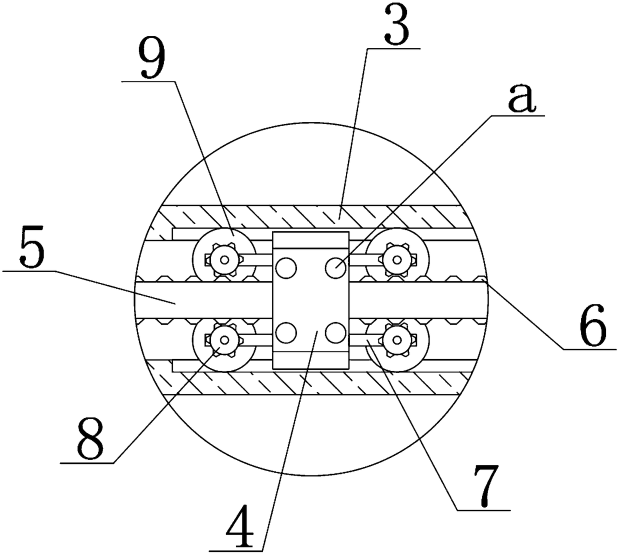
[0019] see Figure 1-3 , the present invention provides a technical solution:

[0020] A guide rail for a cutting machine that can be adjusted at an angle, including a base 1, a fixed shaft 2 is fixedly connected to the inner center of the rear end surface of the base 1, and a guide rail 3 is slidably connected to the outer side of the fixed shaft 2, and the guide rail 3 is connected to the base 1 Sliding connection, the front end surface of the fixed shaft 2...


PUM


Abstract

The invention relates to the technical field of guide rails, in particular to an angle-adjustable guide rail for a cutting machine. The guide rail comprises a base, a fixing shaft is fixedly connectedto the center of the inner side of the rear end face of the base, a guide rail body is connected to the outer side of the fixing shaft in a sliding mode, moreover, the guide rail body is in sliding connection with the base, the front end face of the fixing shaft is fixedly connected with a foundation seat, the inner side of the guide rail body is connected with a sliding block in a sliding mode,a threaded hole is formed in the top end face of the sliding block, a sliding rod is connected to the inner side of the sliding block in a sliding mode, moreover, the sliding rod is fixedly connectedwith the guide rail body, racks are fixedly connected to the upper end surface and the lower end surface of the sliding rod, and fixing rods are fixedly connected to the left end face and the right end face of the sliding block. According to the angle-adjustable guide rail for the cutting machine, through the arranged base, the guide rail body can rotate on the base in a sliding mode through the arrangement, therefore, the effect of carrying out multi-azimuth cutting on a cutting part is achieved, the operation of taking down the cutting part for direction adjustment is not needed, so that thetime is saved, and the cutting efficiency is improved.

Description

technical field [0001] The invention relates to the technical field of guide rails, in particular to an angle-adjustable guide rail for cutting machines. Background technique [0002] The guide rail for the cutting machine is to fix the cutting piece first, and then limit the movement track of the cutting machine through the guide rail, so as to cut the cutting piece to obtain the cutting piece of the required length, and avoid the cutting machine from moving during the cutting process. Some shaking and other phenomena appear during the cutting process, so as to ensure the cutting quality and cutting efficiency. Some traditional cutting machines can only change the cutting direction by adjusting the fixed position of the cutting piece when cutting. This operation It seems very time-consuming, therefore, the demand for a cutting machine guide rail that can be adjusted in angle is increasing day by day. [0003] At present, when some cutting machines on the market are perfo...

Claims


Application Information

Patent Timeline
Patent Type & Authority Applications(China)
IPC IPC(8): B23Q1/01
CPCB23Q1/017
Inventor 不公告发明人
Owner WUHU CHUANGYUAN NEW MATERIALS CO LTD
Learn More