
CMOS reference source circuit

A reference source circuit and reference current technology, applied in the direction of adjusting electrical variables, control/regulation systems, instruments, etc., can solve the problems of poor compatibility of bipolar devices, reduce the output reference voltage value, and increase the difficulty of design, etc. , to achieve the effect of low power consumption, reduced difficulty, and fast switching speed

Inactive Publication Date: 2007-07-25
海安江理工技术转移中心有限公司 +1
View PDF0 Cites 31 Cited by
  • Summary
  • Abstract
  • Description
  • Claims
  • Application Information

AI Technical Summary

Problems solved by technology

However, there are many problems in the realization of the bandgap reference voltage source in the CMOS process, so its development is limited by many factors, and there are the following problems: due to the poor compatibility of the bipolar device in the CMOS process, the Therefore, the bandgap reference voltage source implemented on the CMOS process line will have the problem of whether the triode can be accurately realized and how to reduce the amplifier offset
The more commonly used reference current sources mainly adopt a Vth-based self-bias structure. This reference current source has the disadvantage of poor temperature coefficient.
[0005] In addition, some application systems require a reference voltage value lower than 1V. The general bandgap reference voltage source cannot directly meet this requirement. It is necessary to design other voltage conversion circuits to reduce the output reference voltage value, which will also increase the design cost. difficulty

Method used


Image

  • CMOS reference source circuit
  • CMOS reference source circuit
  • CMOS reference source circuit

Examples


Embodiment Construction

[0018] The purpose, circuit structure and advantages of the present invention will be further described below through specific embodiments of the present invention in conjunction with the accompanying drawings.

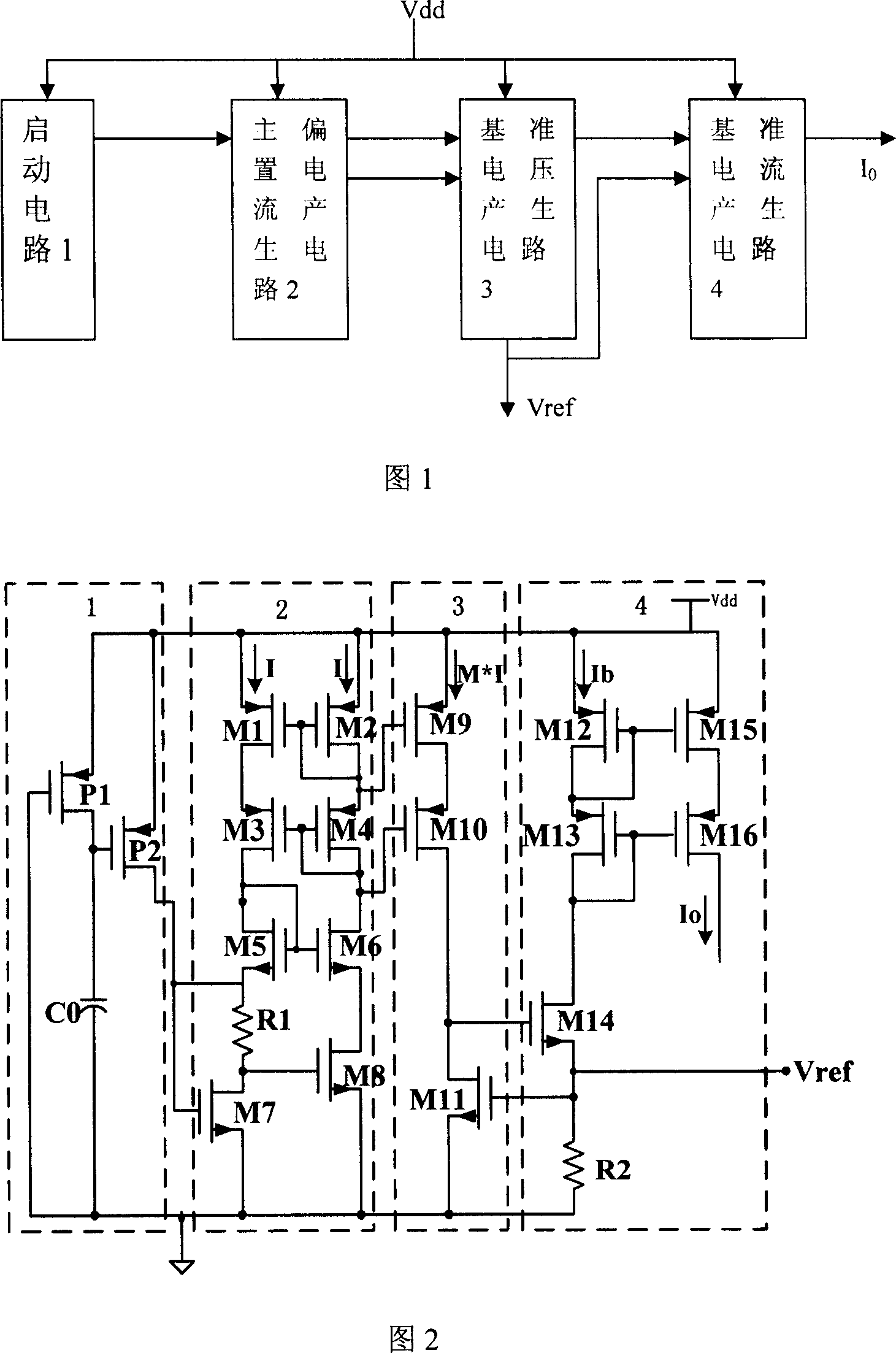
[0019] As shown in Figure 1, the CMOS reference source circuit includes a start-up circuit 1 used to make the reference circuit break away from zero steady state and turn into a normal working state, a bias circuit used to generate a main bias current and a main bias current generating circuit 2, The reference voltage generation circuit 3 and the reference current generation circuit 4, the start-up circuit 1, the main bias current generation circuit 2, the DC input terminals of the reference voltage generation circuit 3 and the reference current generation circuit 4 are respectively connected to the DC power supply Vdd, and the main bias current generation circuit The input terminal of the circuit 2 is connected to the output terminal of the start-up circuit 1, and the...


PUM


Abstract

A circuit of CMOS reference source is prepared for connecting DC input end of start-up circuit, master offset current generating circuit, reference voltage generating circuit and reference current generating circuit separately to DC source, connecting master offset current generating circuit to start-up circuit and to reference voltage generating circuit being connected with reference current generating circuit, outputting reference voltage by reference voltage output end being connected to reference current generating circuit and outputting reference current by reference current generating circuit.

Description

technical field [0001] The invention relates to a reference source circuit for low temperature coefficient and high power supply rejection ratio which needs to be generated in analog and digital-analog hybrid circuits, in particular to a CMOS reference source circuit. Background technique [0002] Reference source circuits are often used in analog, digital-analog hybrid, especially pure digital circuits, including reference voltage sources and reference current sources. The stability of the reference source circuit is directly related to the performance of the whole circuit. The reference voltage source is directly related to the value of the output voltage and the working state of the comparator. The reference current source provides current for each module of the system, and its performance has a great influence on the operating frequency of the oscillator, the working state of the comparator and the operational amplifier. In existing circuits, a reference voltage source...

Claims


Application Information

Patent Timeline
Patent Type & Authority Applications(China)
IPC IPC(8): G05F3/24
Inventor 孙伟锋夏晓娟谢亮时龙兴
Owner 海安江理工技术转移中心有限公司
Learn More