
Jet type electrostatic spinning equipment capable of producing Nano fiber in bulk

A nanofiber and electrospinning technology, applied in fiber processing, spinneret assemblies, textiles and papermaking, etc., can solve problems such as difficulties, low spinning efficiency and output, spinneret electric field interference, etc., and achieve production efficiency high effect

Inactive Publication Date: 2007-07-25
DONGHUA UNIV
View PDF12 Cites 113 Cited by
  • Summary
  • Abstract
  • Description
  • Claims
  • Application Information

AI Technical Summary

Benefits of technology

This technology allows for efficient manufacturing of fibers with very small diameters while avoiding repeated replacements or drilling through other parts of the device's interior. It also enables mass producing these fiber materials at an affordable cost compared to traditional methods like spinning techniques used today.

Problems solved by technology

The technical problem addressed in these inventions relates to improving the quality and consistency of producing high-quality fibers by reducing variations caused during manufacturing processes that can affect their properties (such as strength).

Method used


Image

  • Jet type electrostatic spinning equipment capable of producing Nano fiber in bulk
  • Jet type electrostatic spinning equipment capable of producing Nano fiber in bulk

Examples


Embodiment 1

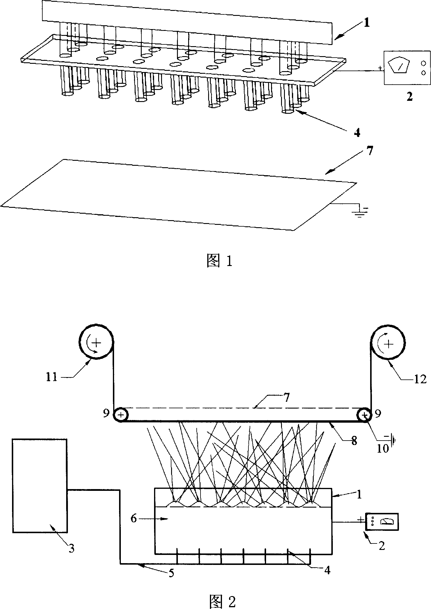
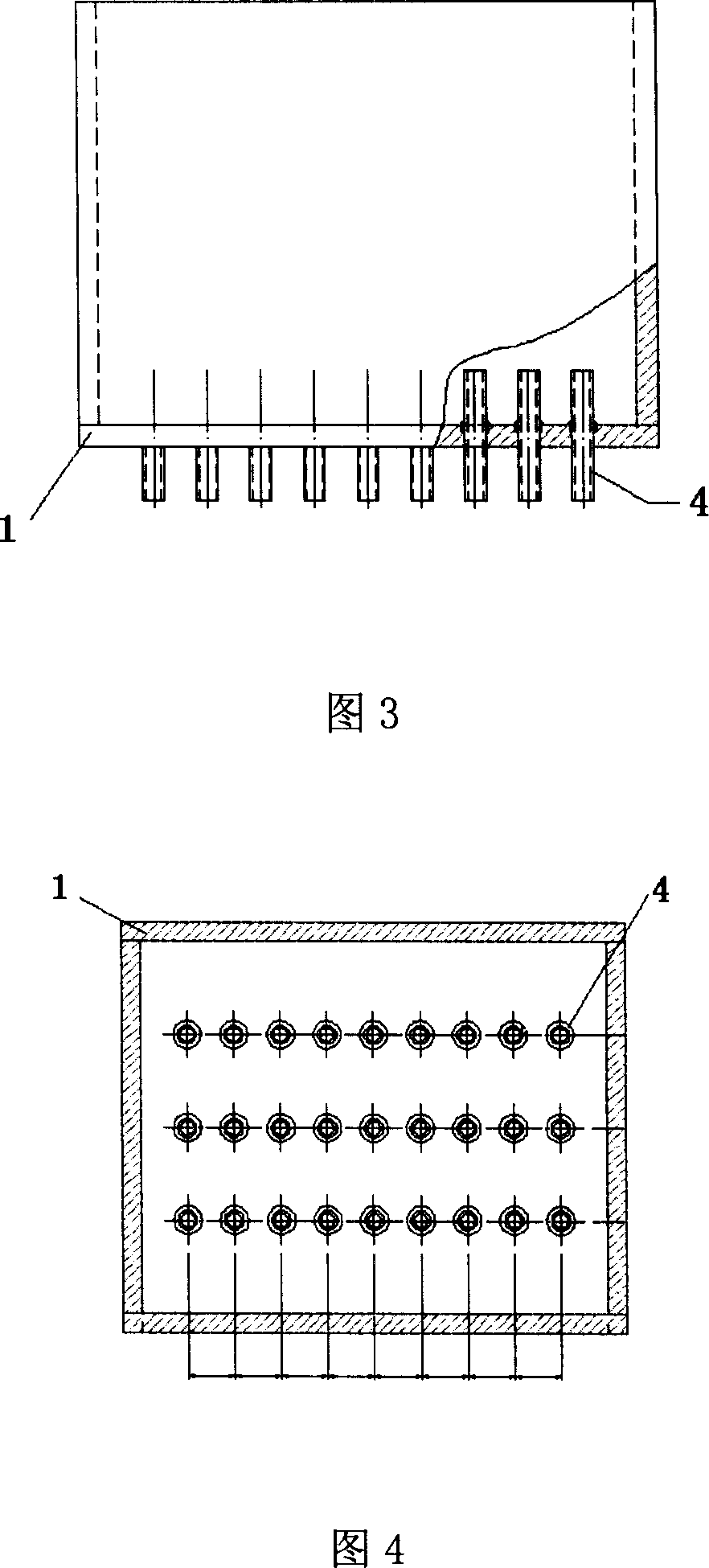
[0016] An air-jet electrospinning device that can be used for mass production of nanofibers, including a liquid storage tank 1, a high-voltage electrostatic generator 2, a nozzle 4, an air pump 3 and a receiving plate 7, and the upper end of the liquid storage tank 1 is open , the bottom surface of the liquid storage tank 1 is provided with vertically upward nozzles 4 arranged in a matrix, the nozzles 4 are connected to the air pump 3 through the air guide tube 5, and the connection between the conduit and the air pump 3 is higher than the liquid level of the liquid storage tank 1, and the liquid storage tank 1 passes through The metal electrode is connected to the high-voltage electrostatic generator 2. A transmission device and a receiving curtain 8 are arranged directly above the liquid storage tank 1. The transmission device is composed of a receiving plate 7 and a guide roller 9. The receiving plate 7 is connected to the ground electrode through the guide roller 9. 10 is c...


PUM


Abstract

The present invention discloses an air-jet type electrostatic spinning equipment for large lot production of nanofibre. Said equipment includes the following several portions: storage liquor tank, high-voltage electrostatic generator, spray head, air pump, receiving electrode plate, air-duct, receiving curtain, guiding roller, ground electrode withdrawal roller and winding roller. Besides, said invention also provides the connection mode of all the above-mentioned portions.

Description


Claims


Application Information

Patent Timeline
Owner DONGHUA UNIV
Learn More