
Method and device for measuring pollutant discharging total of motor vehicle

A pollutant emission and measurement device technology, which is applied in the direction of measurement devices, vehicle testing, engine testing, etc., can solve the problems of large influence of zirconia oxygen sensor, large dilution ratio error, error, etc., and achieve high exhaust gas detection accuracy, The effect of improving accuracy

Inactive Publication Date: 2007-07-18
WUHAN CUBIC OPTOELECTRONICS
View PDF3 Cites 37 Cited by
  • Summary
  • Abstract
  • Description
  • Claims
  • Application Information

AI Technical Summary

Problems solved by technology

O as a tracer gas 2 or CO 2 Concentration change is very small, very small error (such as O 2 When the error is an absolute percentage of 0.1%, CO 2 When the error is an absolute percentage of 0.04%), it may cause a large error in the calculated dilution ratio
In addition, foreign patents use zirconia oxygen sensors as a tracer method for diluted exhaust gas, but electrochemical sensors are used for oxygen detection in undiluted exhaust gas. The response time of the two is very different, and it is difficult to achieve transient response.
Moreover, CO and HC in the diluted exhaust gas have a great influence on the zirconia oxygen sensor, which is easy to cause large errors
Domestic use of CO 2 Although the tracer method solves the problem of transient response, the CO 2 Tracing is easy to cause large dilution ratio errors, which has also been proved by a large number of domestic experiments
The above analysis shows that the previous methods are not suitable for the measurement of the exhaust gas of a large number of motor vehicles with a displacement of 0.8L-1.8L in my country, and at the same time cannot meet the requirements of the simple transient working condition method for vehicles in use in my country

Method used

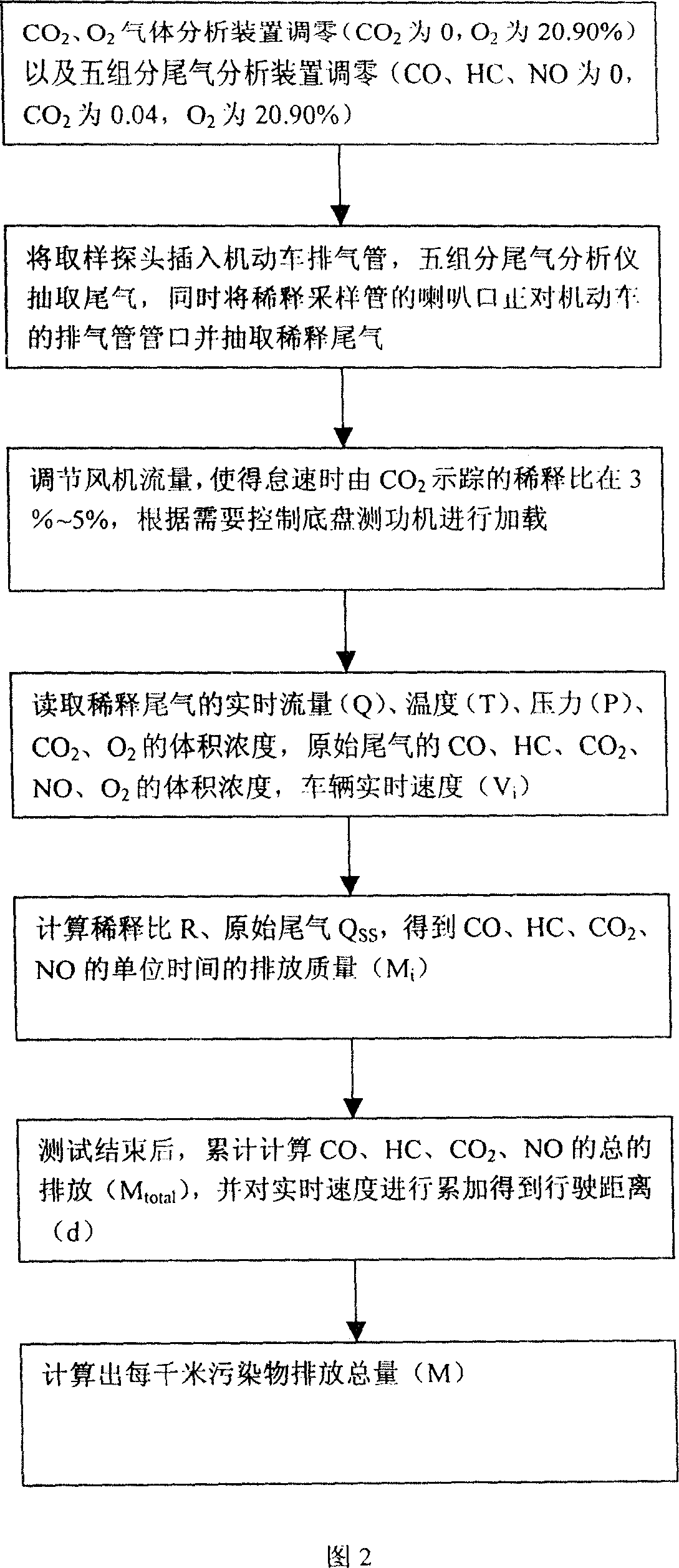

Image

  • Method and device for measuring pollutant discharging total of motor vehicle
  • Method and device for measuring pollutant discharging total of motor vehicle

Examples


Embodiment Construction

[0016] Referring to Fig. 1, the inlet of the diluted sampling pipe 2 with bell mouth is connected to the exhaust pipe of the motor vehicle under test, the outlet is connected to the fan 3, the fan 3 is connected to the fan flow regulating device 4, and the control interface of the computer measurement and control system 9 is connected to the chassis dynamometer 1 and fan flow regulating device 4, flow, temperature, pressure measuring device 5, five-component tail gas analysis device 6, O 2 Gas analysis device 7, CO 2 The interface of the gas analysis device 8 is connected to the computer measurement and control system 9 . The output end of the sampling probe 10 is connected to the five-component exhaust gas analysis device 6, and the input end is located in the exhaust pipe of the motor vehicle.

[0017] o 2 Gas analysis device 7, CO 2 The gas analysis device 8 samples from the rear sampling port of the flow, temperature and pressure measuring device 5, and directly measure...


PUM


Abstract

The invention relates to vehicle pollutant discharging total measuring device and method. The device is made up of diluting sampling tube, fan, computer measure-control system, chassis power measuring machine, fan flow rate adjusting device, flow rate, temperature, and pressure measuring devices, five components tail gas, O2, CO2 gas analysis devices. The measuring method includes the following steps: using fan flow rate adjusting device to control pumping drainage fan, measure diluted tail gas flow rate, temperature, pressure, O2, CO2 volume density; using five components gas analysis device to measure undiluted tail gas for each gas volume density; calculating out the undiluted tail gas flow rate by the volume density ratio to gain vehicle pollutants discharging gross. The invention has high detecting precision for tail gas, can be used in pollutants discharging gross detecting for vehicle operating condition method tail gas detecting line or repair shop.

Description

technical field [0001] The invention relates to a measuring device and method for the total discharge of motor vehicle pollutants. Background technique [0002] With the rapid increase in automobile production and sales in recent years, the generation of a large number of automobile pollutants has become a common social problem. In some cities, motor vehicle pollution has become the number one source of pollution in cities. Existing detection methods of automobile exhaust pollutants include FTP, ASM and IM240 methods. The ASM detection method is based on the pollutant emission concentration rather than the total emission, which is unfair to vehicles with different engine displacements, and the total amount of pollutants cannot be counted; the test results of the three pollutants of HC, CO, and NO by the IM240 method Compared with the FTP results, the dispersion is very small, and the false positive rate is very low. However, the equipment cost of the IM240 working condition...

Claims


Application Information

Patent Timeline
IPC IPC(8): G01M15/00G01M15/10G01M17/007G01N33/00
Inventor 熊友辉刘志强蒋泰毅
Owner WUHAN CUBIC OPTOELECTRONICS
Learn More