
Autonomous obstacles surmounting mechanism of grip hook composite type tour inspection robot

An inspection robot and composite technology, applied in locomotives, motor vehicles, overhead lines/cable equipment, etc., can solve the problems of limited obstacle surmounting ability, difficult control, complex structure, etc., and achieve strong obstacle surmounting ability and working space. The effect of large, large working range

Active Publication Date: 2007-07-18
SHENYANG INST OF AUTOMATION - CHINESE ACAD OF SCI
View PDF0 Cites 37 Cited by
  • Summary
  • Abstract
  • Description
  • Claims
  • Application Information

AI Technical Summary

Problems solved by technology

[0003] In order to overcome the disadvantages of the above-mentioned mobile mechanism, such as complex structure, heavy weight, high energy consumption, limited obstacle surmounting ability and difficult control, the present invention provides a wheel-claw compound superstructure with large working space, low energy consumption and strong obstacle surmounting ability. High-voltage transmission line inspection robot autonomous obstacle-crossing mechanism

Method used


Image

  • Autonomous obstacles surmounting mechanism of grip hook composite type tour inspection robot
  • Autonomous obstacles surmounting mechanism of grip hook composite type tour inspection robot
  • Autonomous obstacles surmounting mechanism of grip hook composite type tour inspection robot

Examples


Embodiment 1

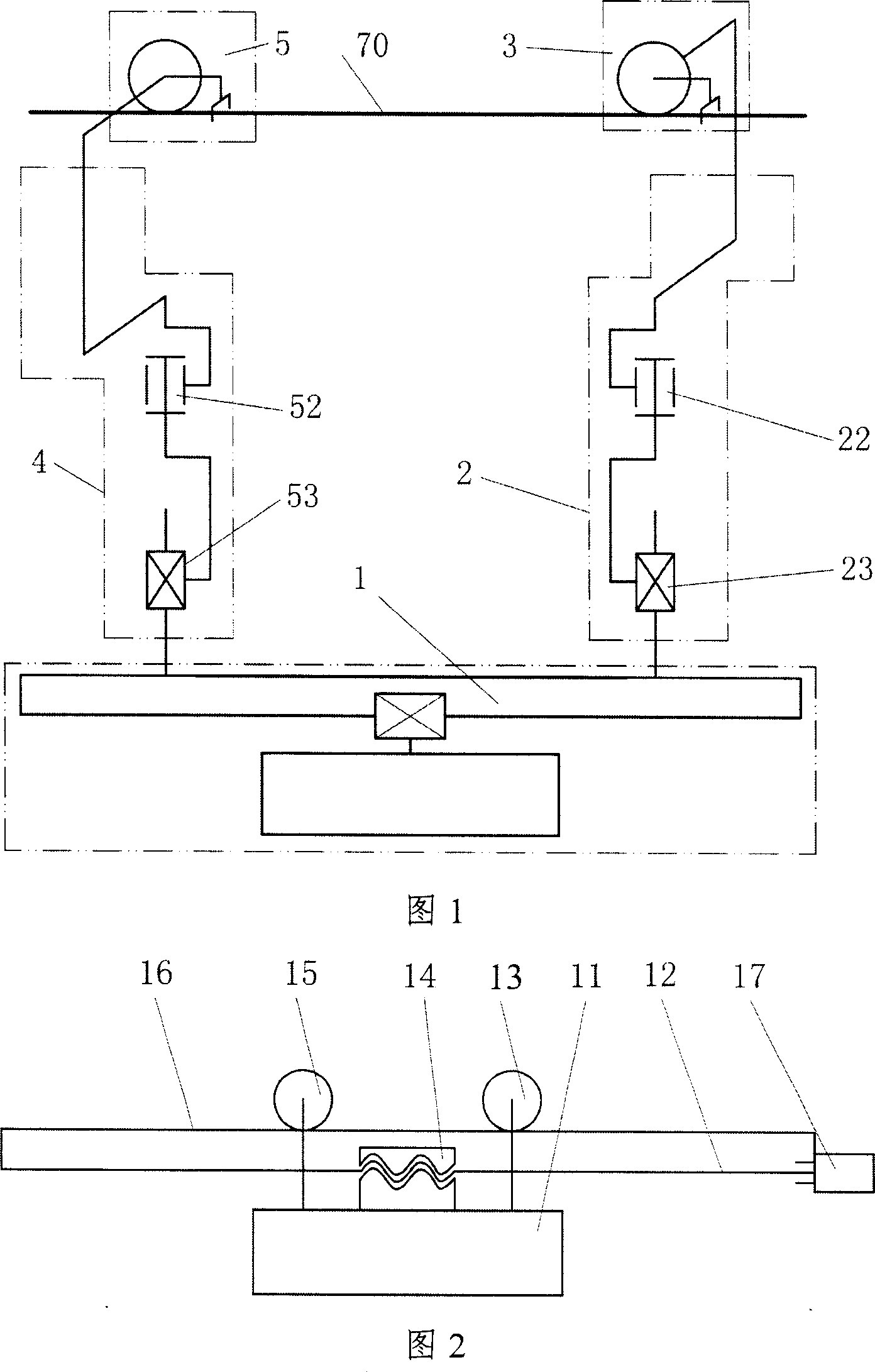
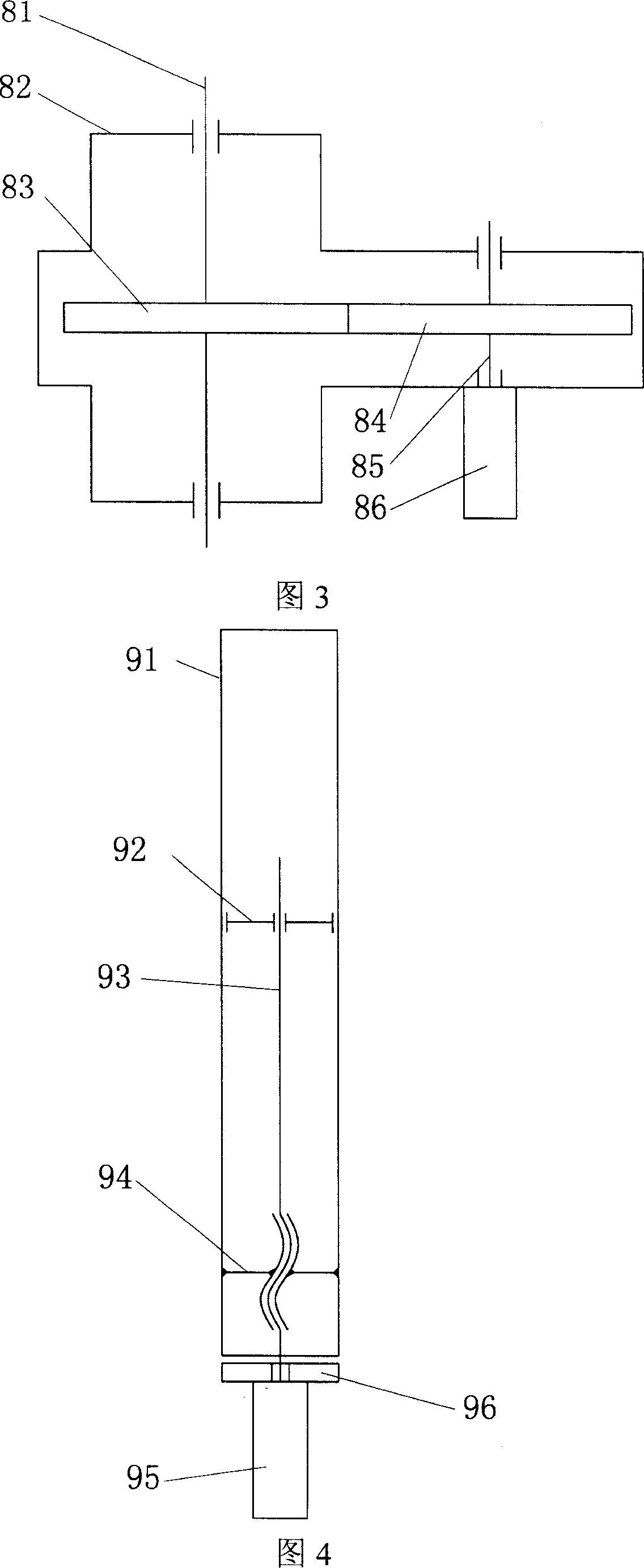
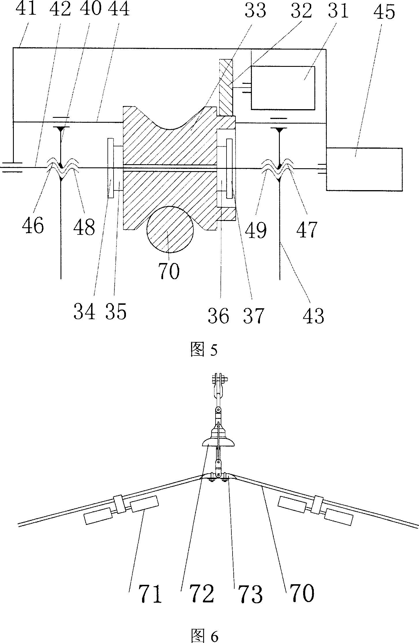
[0025] As shown in Figure 1, the mechanical structure of the present invention is made up of center of mass adjustment mechanism 1, front arm 2, front travel clamping mechanism 3, rear arm 4, rear travel clamping mechanism 5, described front and rear arms 2,4 One end is fixed on the center of mass adjustment mechanism 1 by screws; the other end is connected with the front and rear travel clamping mechanisms 3 and 5, and the arms 2 and 4 are respectively controlled by the front and rear rotary mechanisms 22 and 52, and the front and rear vertical telescopic mechanisms 23. , 53, wherein one end of the front and rear slewing mechanism 22, 52 is directly connected with the front and rear travel clamping mechanism 3, 5, and the other end is connected with the center of mass adjustment mechanism 1 after the front and rear vertical expansion mechanism 23, 53; The walking clamping mechanism is located on the overhead ground; the front and rear walking clamping mechanisms 3, 5 and the f...

Embodiment 2

[0035] The difference from Embodiment 1 is that, as shown in Figure 8, in the center of mass adjustment mechanism 1, the driving reel 12, the passive reel 13, and the cable 14 are used to replace the original screw nut mechanism, further reducing the weight. The flexible cable 14 two ends pass through the active reel 12, the passive reel 13 is connected with the electrical box 11, and the active reel 12 and the motor 17 drive the flexible cable 14 to move, thereby driving the electrical box 11 to move on the carrier plate 16.


PUM


Abstract

The present invention discloses an EHV transmission line patrol robot mechanism. It is formed from mass centre regulation mechanism, front arm, forwards-travelling holding mechanism, rear arm and backwards-travelling holding mechanism. Said invention also provides its working principle and its concrete operation method.

Description

technical field [0001] The invention relates to a mobile robot mechanism, in particular to an autonomous obstacle-surpassing mechanism of a wheel-claw compound inspection robot applied to the inspection of ultra-high voltage transmission lines. Background technique [0002] In the existing ultra-high voltage transmission line inspection robot mechanism, most of them adopt the composite mobile mechanism composed of wheeled mobile and composite linkage mechanism (Document 1: Jun Sawada, Kazuyuki Kusumoto, Tadashi Munakata, Yasuhisa Maikawa, Yoshinobu Ishikawa , "AMobile Robot For Inspection of Power Transmission Lines", IEEE Trans.PowerDelivery, 1991, Vol.6, No.1: pp..309-315; Literature 2: Mineo Higuchi, Yoichiro Maeda, Sadahiro Tsutani, Shiro Hagihara, "Development of a Mobile InspectionRobot for Power Transmission Lines", J.of the Robotics Society of Japan, 1991, Vol.9, No.4, pp..457-463), or a multi-degree-of-freedom movement composed of multiple sets of mobile units conne...

Claims


Application Information

Patent Timeline
IPC IPC(8): B61C13/06B62D57/028H02G1/02
Inventor 王洪光房立金朱兴龙
Owner SHENYANG INST OF AUTOMATION - CHINESE ACAD OF SCI
Learn More