Probe for an atomic force microscope

An atomic force microscope, a microscope technology, applied in scanning probe technology, scanning probe microscopy, measuring devices, etc., can solve problems such as inability to measure interaction force

Inactive Publication Date: 2010-02-24
INFINITESIMA
View PDF12 Cites 0 Cited by
  • Summary
  • Abstract
  • Description
  • Claims
  • Application Information

AI Technical Summary

Problems solved by technology

if τ res > f r , then obviously the interaction force cannot be accurately measured from one pixel to another

Method used


Image

  • Probe for an atomic force microscope
  • Probe for an atomic force microscope
  • Probe for an atomic force microscope

Examples


Embodiment Construction

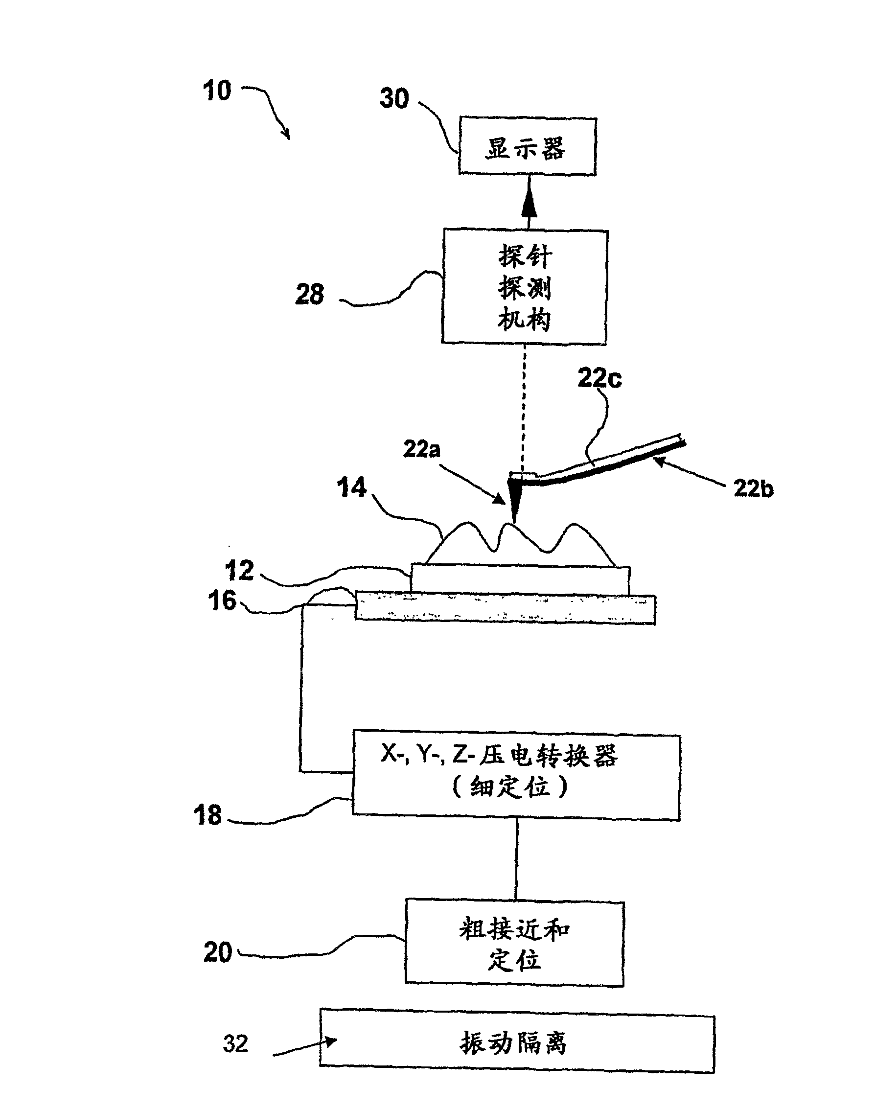
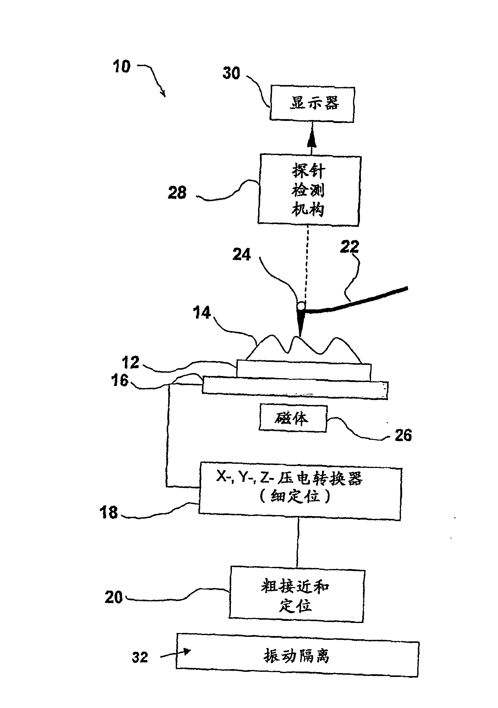
[0046] reference figure 2 A schematic implementation of the AFM indicated generally by 10 is shown, which uses a first embodiment of a probe constructed in accordance with one aspect of the present invention. The illustrated AFM device 10 includes a flat plate 12 suitable for carrying a sample 14 and mounted on a fork arm of a tuning fork 16. The tuning fork 16 is connected to the piezoelectric transducer 18 and the coarse drive device 20. Piezoelectric transducer 18 is used to drive sample 14 (together with plate 12 and tuning fork 16) in the three dimensions x, y, and z directions. In the art, the z-axis of the Cartesian coordinate system is generally perpendicular to the plane occupied by the sample 14. That is, the interaction force depends not only on the xy position (imaged pixel) of the probe 22 above the sample 14, but also on its height above. The tuning fork control (not shown) is arranged to apply a sinusoidal voltage to the tuning fork 16 to excite resonance or n...


PUM


Abstract

A probe (22) for an atomic force microscope is adapted such that, as a sample (14) is scanned, it experiences a biasing force Fdirect urging the probe towards the sample. This improves probe trackingof the sample surface and faster scans are possible. This is achieved by either including a biasing element (24, 50), which is responsive to an externally applied force, on the probe (22) and / or reducing the quality factor of a supporting beam. The biasing element may, for example, be a magnet (24) or an electrically-conducting element (50). The quality factor may be reduced by coating the beamwith a mechanical-energy dissipating material.

Description

Technical field [0001] The present invention relates to the field of atomic force microscopes, probes used in such microscopes, and methods of operating such microscopes. In particular, it relates to an atomic force microscope that does not utilize conventional feedback control of the probe height. Background technique [0002] The atomic force microscope (AFM) or scanning force microscope (SFM) was invented in 1986 by Binnig, Quat, and Gerber. Like all other scanning probe microscopes, AFM is based on the principle of mechanically scanning nanoprobes over the sample surface in order to obtain an "interaction profile" of the sample. The interaction force in this case is only the molecular interaction between the sample and the tip of the sharp probe attached to the cantilever spring. When the probe tip begins to approach the sample in close proximity, the cantilever bends in response to the interaction force. Images are collected by scanning the sample relative to the probe an...

Claims


Application Information

Patent Timeline
Patent Type & Authority Patents(China)
IPC IPC(8): G01Q10/06G01Q60/38
CPCG01Q10/06
Inventor 安德鲁·大卫·拉维尔·哈姆菲里斯杰米·凯恩·霍博斯默文·琼·迈尔斯
Owner INFINITESIMA
Why Eureka
Try Eureka