Controlled train tail apparatus

A technology of driver control and GSM-R, which is applied in the field of railway transportation equipment and train tail devices, can solve the problems affecting the safety and efficiency of train operation, communication reliability and real-time performance that cannot fully meet actual needs, and can not be fully acted at the same time , to achieve the effect of improving the train braking effect, shortening the train braking distance and speeding up the train braking speed

Inactive Publication Date: 2010-02-17
BEIJING JIAOTONG UNIV
View PDF1 Cites 0 Cited by
  • Summary
  • Abstract
  • Description
  • Claims
  • Application Information

AI Technical Summary

Problems solved by technology

[0003] At the same time, the transmission of decompression and exhaust commands between the tail unit and the lead locomotive still relies on the traditional analog communication method. The reliability and real-time performance of the communication cannot fully meet the actual needs, which seriously affects the safety and efficiency of train operation.
[0004] In the field of railway transportation, especially when heavy-duty long trains are braking, due to the long distance between the head and the tail of the train, the decompression and exhaust effect of the main locomotive cannot be fully applied to the entire train at the same time, which will cause the braking speed of the entire train to decrease. Slow, large longitudinal impulse of the train, long braking distance of the train, etc., so the main locomotive at the head of the train and the rear of the train must perform synchronous exhaust braking
The function and performance of the existing train tail device cannot meet the control requirements of the main locomotive at the head of the heavy-duty train and the rear of the train for simultaneous exhaust and decompression

Method used


Image

  • Controlled train tail apparatus

Examples


Embodiment Construction

[0017] The present invention will be further described below in conjunction with accompanying drawing:

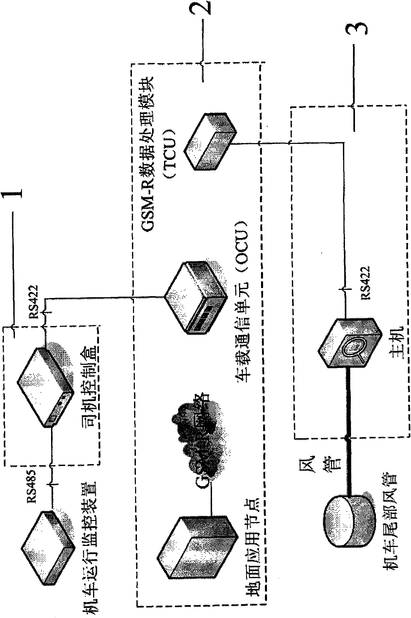
[0018] A controllable train tail device includes: a driver control box 1 , a data wireless transmission device 2 and a host computer 3 .

[0019] The driver control box 1 is connected with the locomotive running monitoring device through the RS485 type serial port.

[0020] Data wireless transmission equipment 2 comprises: ground application node, GSM-R network, vehicle communication unit (OCU), GSM-R digital processing module (TCU); Vehicle communication unit (OCU) and GSM-R data processing module (TCU) pass The GSM-R network is connected to the ground application node; the ground application node is installed in the ground machine room, the on-board communication unit (OCU) is installed in the cab of the locomotive, and the GSM-R data processing module (TCU) is installed at the rear of the train; the on-board communication unit ( OCU) is connected with the driver control...


PUM


Abstract

The invention discloses a controllable train rear device, and belongs to a railway transportation field. The device comprises a driver control box connected with a locomotive operation monitoring device via a RS485 serial port; a data wireless transmission device including a ground application node, a GSM-R network, a vehicle-carried communication unit (OCU), and a GSM-R digital processing module(TCU). The vehicle-carried communication unit (OCU) and the GSM-R digital processing module (TCU) are connected with the ground application node. The ground application node is disposed in a ground machine room. The vehicle-carried communication unit (OCU) is disposed in the driving cab of a train locomotive. The GSM-R digital processing module (TCU) is disposed at the train rear. The vehicle-carried communication unit (OCU) is connected with the driver control box via a RS422 serial port. A mainframe is connected with the GSM-R digital processing module (TCU) via a RS422 serial port. With thedevice, the front and rear portions of the train can be synchronously braked.

Description

technical field [0001] The invention relates to a train tail device, which realizes the controllability of the air exhaust and decompression amount at the tail of the train and the synchronization with the air exhaust of the leading locomotive. It belongs to the field of railway transportation equipment technology and equipment. Background technique [0002] At present, the functions and functions of the tailing devices produced by various manufacturers in China and the tailing devices produced abroad are similar. Although all have the function of exhaust and decompression, the setting of this function is only for assisting the lead locomotive to brake the train under the situation of weak train braking (generally when the corner cock of the vehicle is closed). Its braking function is the maximum decompression in emergency braking or normal braking, and does not have a synchronous braking function that can control the decompression amount. [0003] At the same time, the tr...

Claims


Application Information

Patent Timeline
Patent Type & Authority Patents(China)
IPC IPC(8): H04L12/28G05B19/418B61C17/12B61L23/00G08C17/00
Inventor 耿志修穆建成钟章队
Owner BEIJING JIAOTONG UNIV
Why Eureka
Try Eureka