Method for correcting multi-screen connected wall
A calibration method and multi-screen technology, applied in color TV, instrument, electrical digital data processing, etc., can solve the problems of large amount of data, complex operation, large error, etc.
- Summary
- Abstract
- Description
- Claims
- Application Information
AI Technical Summary
Problems solved by technology
Method used
Image
Examples
Embodiment 1
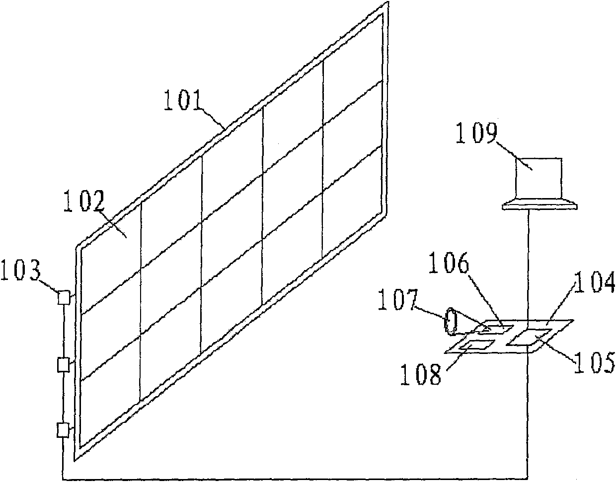
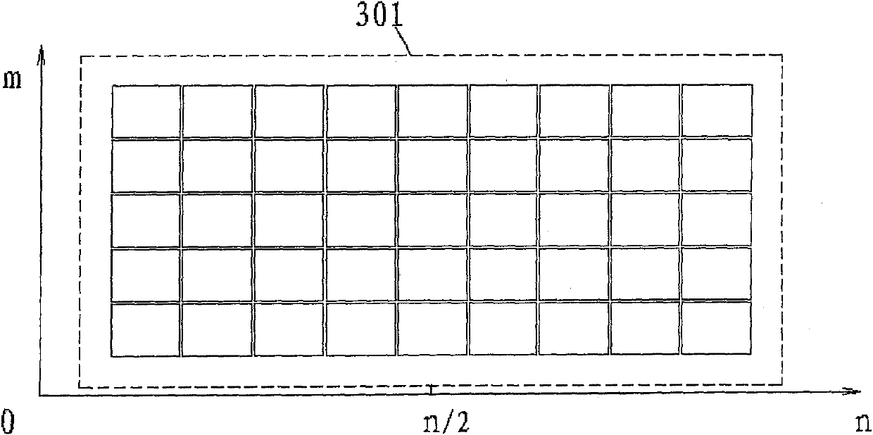
[0051] m×n (m: the number of rows that make up the multi-screen wall, n: the number of columns that make up the multi-screen wall) the schematic diagram of the multi-screen wall color correction method is as follows Figure 4 , place the correction device in front of the screen at a position where the entire display area 401 can be photographed, control the display screen to display a picture of a specified color, take a picture of the screen, extract the color information of the display unit from the picture, and use the central display unit 402 as a benchmark to move to the four directions The three directions 403, 404, 405, 406 are adjusted synchronously, and then adjusted from inside to outside in each small area, such as 407, 408, 409, 410 and so on. The unadjusted display unit is adjusted step by step based on the adjusted display unit, and the adjusted display unit can be properly adjusted as required.
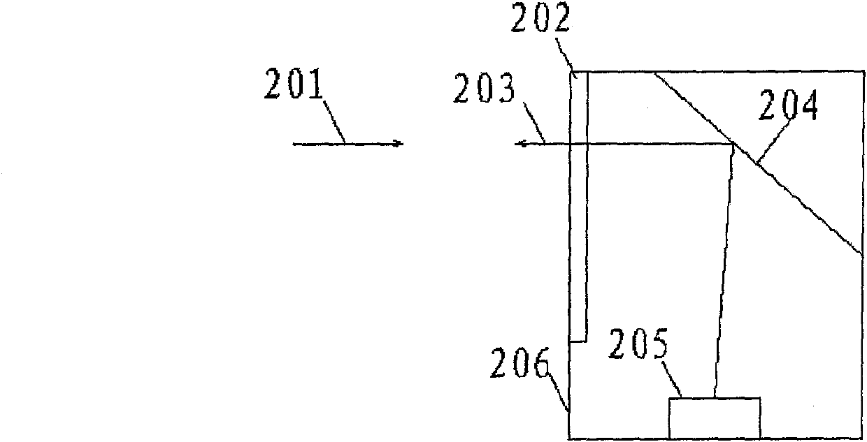
[0052] The computer sends commands to the calibration device to co...
Embodiment 2
[0058] The schematic diagram of the multi-screen wall color method of partition correction m×n is as follows Figure 5 , divide the screen into four 501, 502, 503, 504 or more correction areas, and every two adjacent correction areas overlap one row or one column of display units. The four-region correction method is as follows:
[0059] First zone correction: in Figure 6 In the center, 601 is the first correction area, 602 is the reference display unit, and the row where 602 is located is gradually corrected to the left, and the column where 602 is located is corrected upward, and the corrected display unit is used as a new benchmark, and its adjacent display units are gradually corrected , and finally correct 601 the entire display area.
[0060] Second zone correction: in Figure 7 701 is the second correction area, and the display unit in the column of 702 is 701 and Figure 6 In the overlapping area of the 601 correction area, the display units in this column have ...
PUM
 Abstract
Description
Claims
Application Information
 - R&D
- Intellectual Property
- Life Sciences
- Materials
- Tech Scout
- Unparalleled Data Quality
- Higher Quality Content
- 60% Fewer Hallucinations
Browse by: Latest US Patents, China's latest patents, Technical Efficacy Thesaurus, Application Domain, Technology Topic, Popular Technical Reports.
© 2025 PatSnap. All rights reserved.Legal|Privacy policy|Modern Slavery Act Transparency Statement|Sitemap|About US| Contact US: help@patsnap.com


