
Trip edge snow plow blade

A kind of edge and snow plow technology, applied in the direction of snow surface cleaning, construction, cleaning methods, etc., can solve the problems of snow plow blade damage, damage, invisible edge stones, etc., and achieve the effect of preventing damage

Inactive Publication Date: 2010-02-03
SNO WAY INT
View PDF12 Cites 0 Cited by
  • Summary
  • Abstract
  • Description
  • Claims
  • Application Information

AI Technical Summary

Problems solved by technology

[0013] Third, most of the currently known joint edge snow plows are very susceptible to damage caused by striking snow-covered kerbstones, which cannot be seen by the driver of the truck on which the snow plow is mounted.
Since most curbstones are formed at a standard height of 6 inches (15.24 cm), those of ordinary skill in the art immediately know that if a snow plow with such a shorter joint edge knife hits a curbstone, the joint The edge knives are tripped and the bottom of the upper knives also hit the curb stone, potentially causing greater damage to the snow plow blades

Method used


Image

  • Trip edge snow plow blade
  • Trip edge snow plow blade
  • Trip edge snow plow blade

Examples


Embodiment Construction

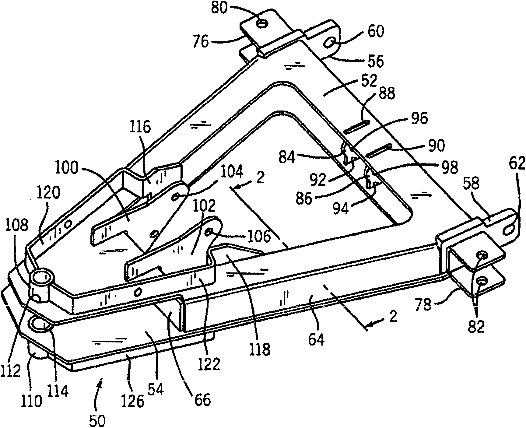
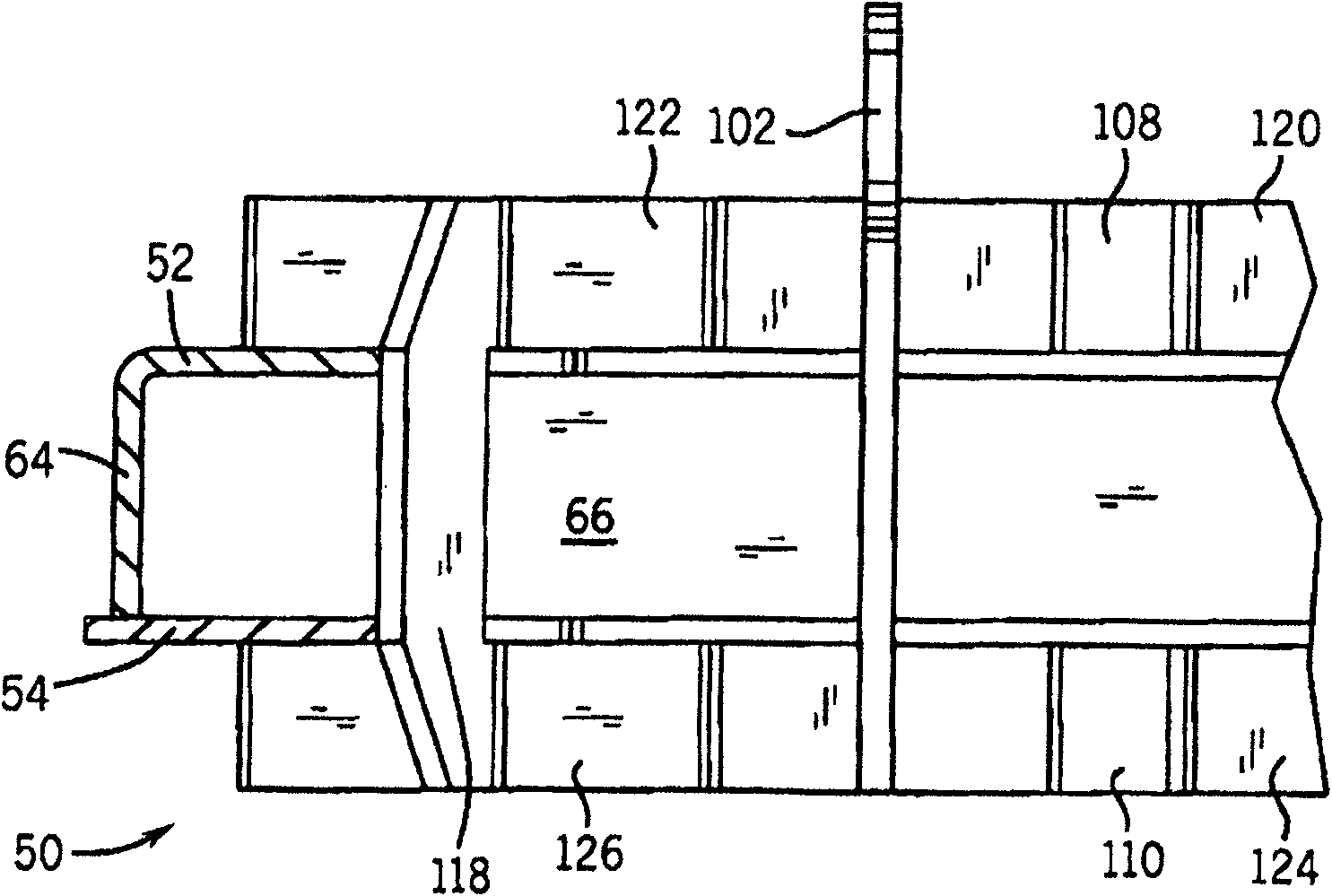
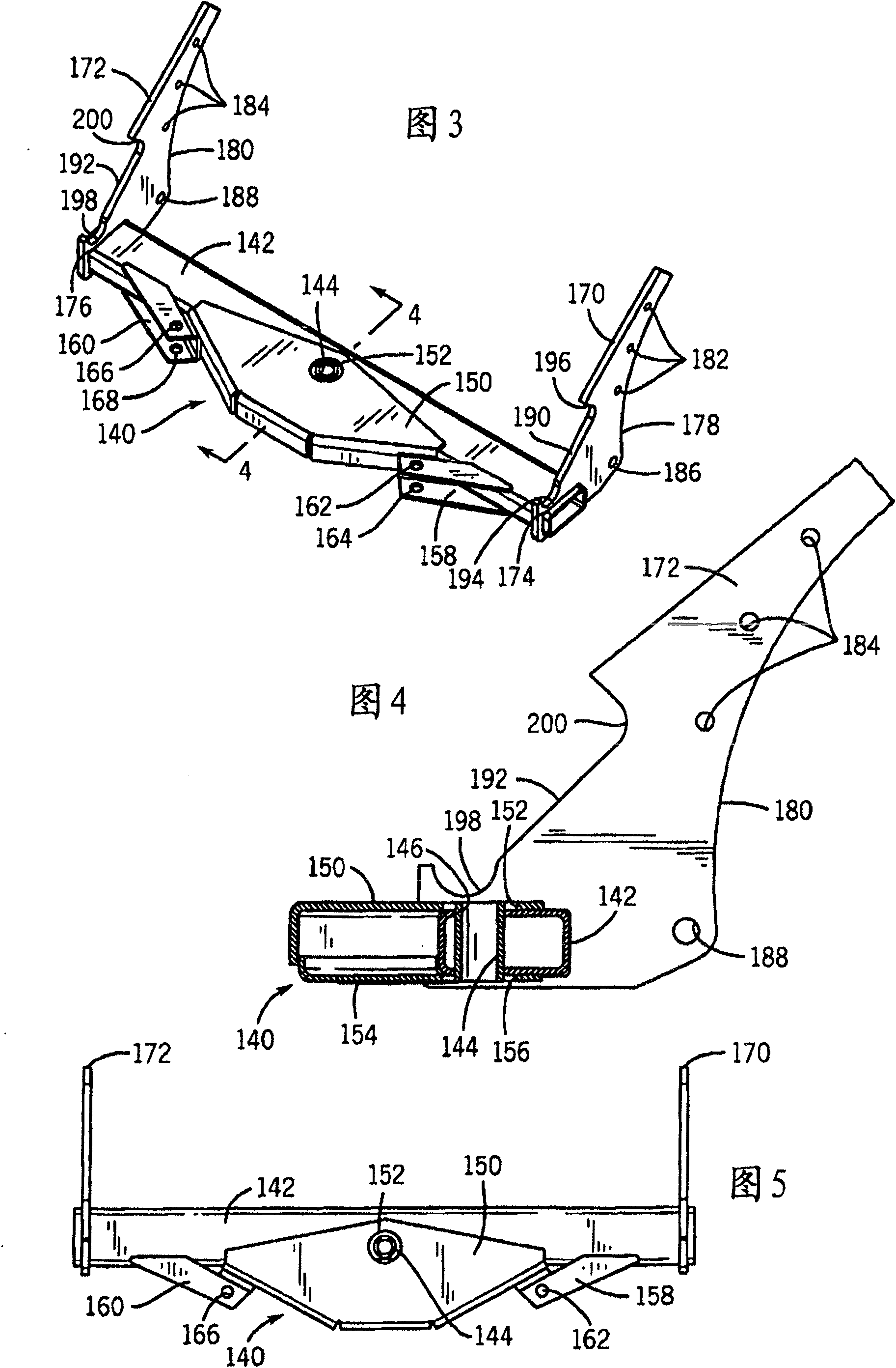
[0061] A preferred embodiment of the trip edge snow plow blade of the present invention is shown in a series of drawings in which the Figures 3 to 5 and 11 to 17 show some parts of an edge-engaging snowplough embodying the invention. Figures 18 to 26 An assembly of edge-engaging snow coulters embodying the invention is shown, Figure 27-29 The working method of the joint edge snow coulter of the present invention is shown. Figures 30 to 32 The assembled joint edge snow coulter of the present invention is shown.

[0062] figure 1 , 2 , 6, 8 and 9 are parts of the snow plow frame on which the joint edge snow plow cutters of the present invention are mounted. Figure 7 is the hitch frame nose piece mounted on the truck to which the snow plow frame is mounted. Figure 10 Shown are the assembled parts of the snow plow frame and the installation of the snow plow frame on the hitch frame nose. Figure 33 The assembled joint edge snow plow cutter of the present invention is s...


PUM


Abstract

An improved snow plow blade is disclosed which has a fixed upper plow blade and a pivoting lower trip blade mounted on the swing frame of the snow plow with the axis of rotation of the trip blade being directly in line with the swing frame and the support frame of the snow plow. Since the axis of rotation of the trip edge blade is located at the height of the vertical center of the swing frame (and is thereby in the same horizontal plane), the forces imparted to the swing frame will be essentially compressive in nature rather than including a torsional element as well. The trip edge blade andthe trip edge springs used to bias the trip edge blade into an untripped position are substantially supported by the swing frame of the snow plow rather than being supported from the upper plow blade.The trip edge blade is also sufficiently high to prevent damage to the upper snow plow blade due to impacts with curbs or other high obstacles.

Description

technical field [0001] The present invention relates generally to a snow plow for use with light and medium duty trucks, and more particularly to an improved snow plow balde having a fixed upper coulter and a pivoting lower engaging blade (trip blade), the joint knife is mounted on the swing frame of the snow plow, the pivot axis of the joint knife is directly consistent with the swing frame and the support frame of the snow plow. Background technique [0002] Snow plows have been used for decades with light and medium-duty trucks in addition to heavy-duty trucks for urban work. As is to be expected in any technological field presented in that time period, snow plows for light and medium trucks have been greatly improved in a variety of ways in that time to increase the effectiveness of snow plows and improve their use. their convenience. Manufacturers of snow plows for light and medium duty trucks are highly competitive, with manufacturers competing to differentiate snow ...

Claims


Application Information

Patent Timeline
IPC IPC(8): E01H5/06
CPCE01H5/062
Inventor L·W·舒尔茨A·M·施密德R·N·甘布尔二世T·C·文多夫
Owner SNO WAY INT
Learn More