
Linear motor

一种线性电动机、线圈的技术,应用在电动组件、电气元件、机电装置等方向,能够解决速度不均、难冷却、复杂冷却构造等问题,达到利用效率高、机械强度强、简单构造的效果

Inactive Publication Date: 2009-12-23
CHRONOFANG
View PDF5 Cites 2 Cited by
  • Summary
  • Abstract
  • Description
  • Claims
  • Application Information

AI Technical Summary

Problems solved by technology

[0007] The second problem is that although the movable coil part 103 generates a lot of heat, it is difficult to cool it due to its movement, and because it must occupy a large space, it must have a complicated cooling structure in order to realize it.
If the heat generation problem of the movable coil part 103 is not solved, the peripheral temperature of the movable coil part 103 will rise, and for example, deformations such as outward warpage and expansion of the transported body such as a semiconductor wafer mounted on the stage will occur, and it will be difficult to maintain the The accuracy of the conveying body will have a bad influence
[0008] The third problem point, such as Figure 14 In the type shown, since the coil of the movable coil part 103 is cylindrical or rectangular, and the permanent magnets are only provided on two sides facing each other, the effective magnetic flux for thrust generation is small.
If the excitation current of the movable coil part 103 is increased in order to increase the thrust force, it will be more difficult to solve the above-mentioned second problem.
[0009] As a fourth problem, especially in the planar facing type (flat type) linear motor, a plurality of plate-shaped permanent magnets are arranged on the side of the stator, and a plurality of plate-shaped permanent magnets are arranged on the side of the movable element facing it. Coil, at this time, because the permanent magnet and the coil are arranged in a segment structure interrupted therebetween, when the mover moves in the axial direction, there must be regular and continuous phenomena in which the yoke and the permanent magnet attract each other and the positions where they do not attract each other (uneven speed)

Method used


Image

  • Linear motor
  • Linear motor
  • Linear motor

Examples


Embodiment Construction

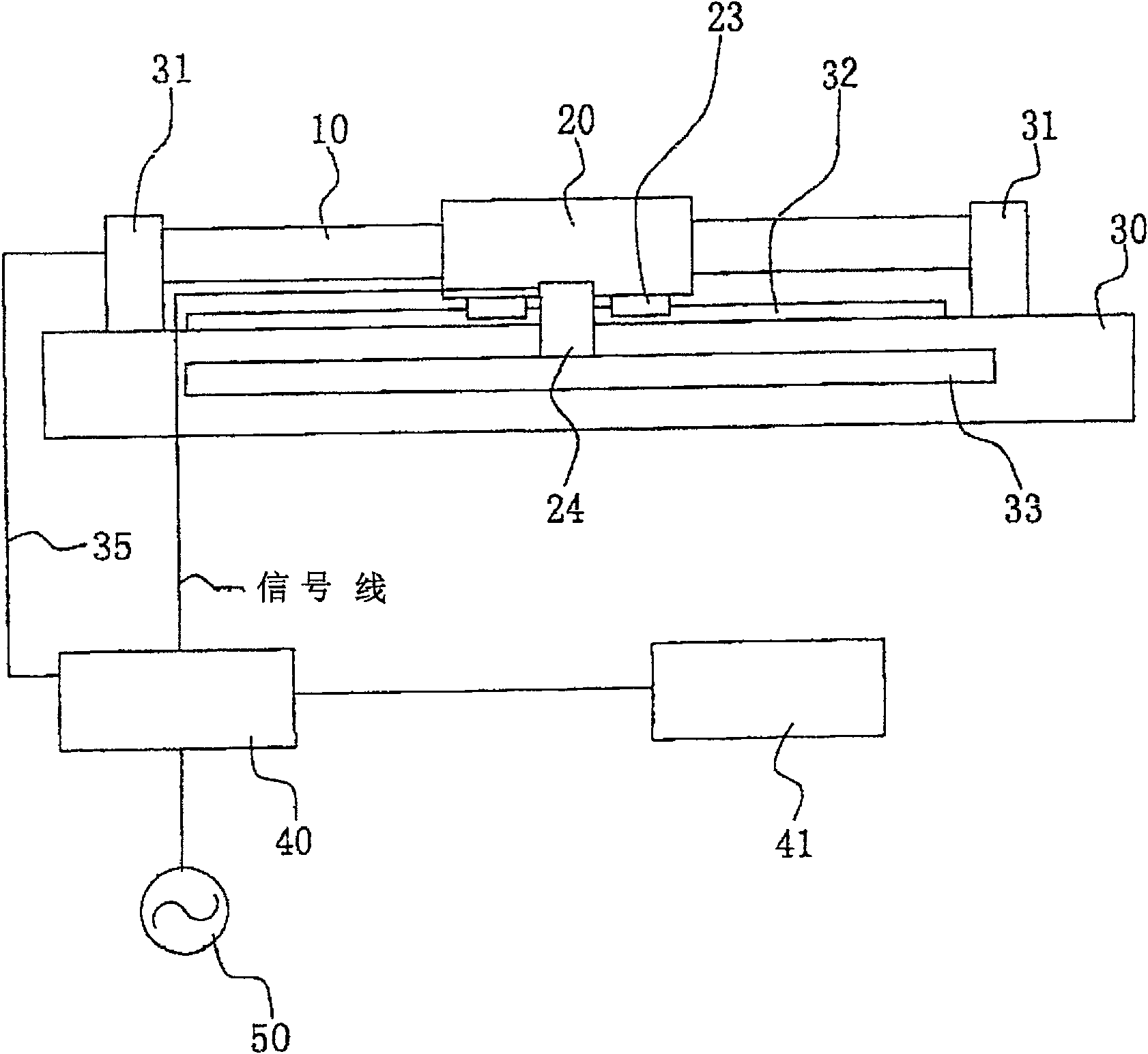
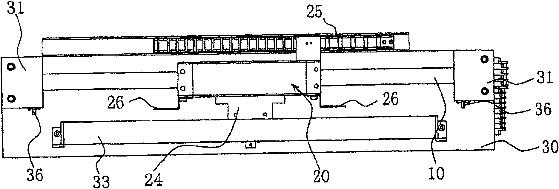
[0097] Hereinafter, a linear motor according to a first embodiment of the present invention will be described. figure 1 shows the schematic composition of a linear motor, Figure 2a to Figure 2d This is a diagram of a linear motor viewed from four directions. which is Figure 2a for the floor plan, Figure 2b for from Figure 2a The side view seen from the underside, Figure 2c for from Figure 2a The side view seen from the upper side, Figure 2d for from Figure 2a Figure seen on the right.

[0098] figure 1 , Figure 2a to Figure 2d Among them, the linear motor includes: a shaft body (hereinafter referred to as a stator) 10 that accommodates a plurality of continuously arranged electromagnet coils (hereinafter referred to as coils); A movable magnet (hereinafter referred to as a mover) 20 that can move in the same direction as the extending direction of 10 . The stator 10 is spanned between two brackets 31 fixed to the base 30 with a certain interval therebetwe...


PUM


Abstract

The present invention provides a linear motor that solves the problem of heat generation of a movable part. The linear motor of the present invention is formed by arranging a plurality of electromagnet coils consecutively and movably assembling permanent magnets under the interaction of magnetic fluxes from these electromagnet coils. Coils for electromagnets include U-phase, V-phase, and W-phase coils (12) connected in a star connection, and these coils of each phase are arranged in series around the hollow shaft-shaped central core (11) throughout the entire moving range of the permanent magnet. Groundly dress, make these magnetic pole axes and the axle center of middle nucleus be the same direction. The permanent electromagnet body has the annular shape that can surround the electromagnet coil, and the magnetic pole axis is formed by a plurality of permanent magnets (21) having 3 times the length of each phase coil, and these plurality of permanent magnets are assembled in series, so that The adjacent magnetic poles are in opposite directions to each other, and the magnetic pole axis and the axis core of the central core are in the same direction.

Description

technical field [0001] This invention relates to linear motors. Background technique [0002] There are various types of linear motors, and most of them are composed of permanent magnets and electromagnet coils unless they require a strong driving force like linear motors driving vehicles. Such a linear motor composed of a combination of a permanent magnet and an electromagnet coil can be considered as a drive source for precision micro-level or precision positioning level, for example, in the field of semiconductor manufacturing equipment. This is because the linear motor drive mechanism has not only high driving speed, but also high positioning accuracy, high repeat positioning accuracy, and overshoot and undershoot that occur when driving and stopping It has the advantage of being relatively small and less speed fluctuation when moving at a constant speed. [0003] refer to Figure 14 , a simple description of a linear motor composed of a combination of permanent magnet...

Claims


Application Information

Patent Timeline
Patent Type & Authority Patents(China)
IPC IPC(8): H02K41/02H02K41/03
CPCH02K41/03
Inventor 渡边浩司
Owner CHRONOFANG
Learn More