Pressure controller
A controller and pressure technology, applied in the direction of fluid pressure control without auxiliary power, safety valve, engine components, etc., can solve the problems of high cost, complex structure, long adjustment stroke, etc., to achieve low cost, compact and simple structure, guiding good effect
- Summary
- Abstract
- Description
- Claims
- Application Information
AI Technical Summary
Problems solved by technology
Method used
Image
Examples
Embodiment 1
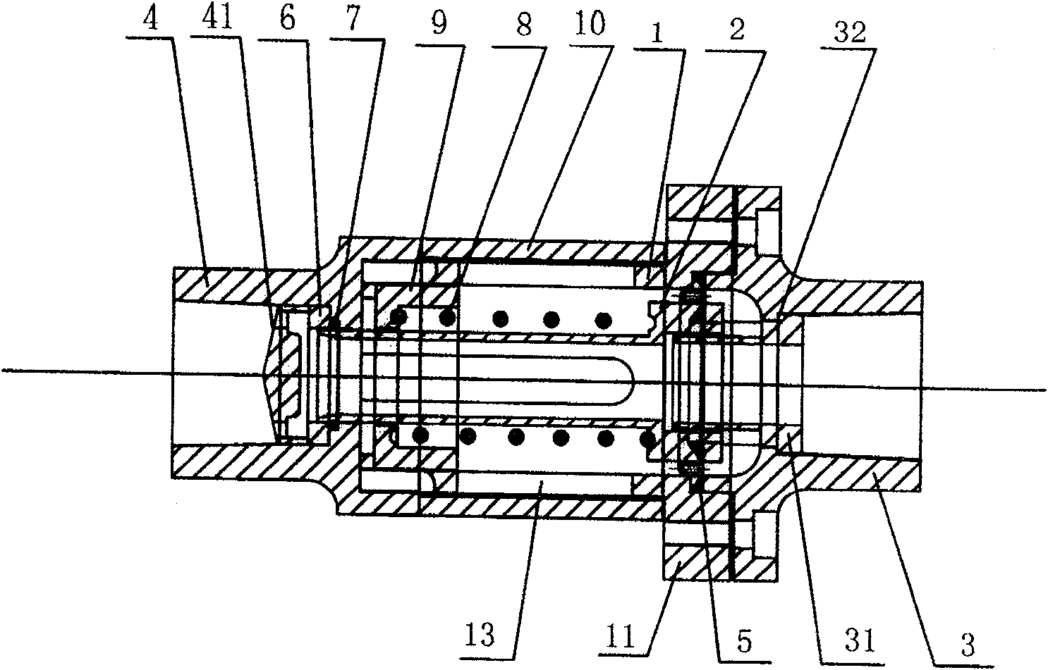
[0026] as attached figure 1 As shown, a pressure controller includes a valve body 1 and a valve core 2 placed therein, and the valve core 2 is hollow. One end of the valve body 1 is provided with a disc-shaped fixed seat 11, and six threaded holes 12 are provided in the circumferential direction. The fixed seat 11 is connected with an outlet valve section 3, which is in the form of a threaded pipe, and the outlet valve section 3 There is a fluid limiter 31 inside, one end of the fluid limiter 31 is clamped on the shoulder 32 in the outlet valve section 3, and the other end is placed in the valve core 2; the outer circumferential direction of the fluid limiter 31 is evenly distributed Stop protrusion 33 is arranged, and the top of spool 2 abuts on the stop protrusion 33 (as Figure 5a , 5b shown). An elastic diaphragm 5 is provided at the joint between the valve core 2 and the valve body 1. One end of the elastic diaphragm 5 is crimped by the outlet valve section 3 and the v...
Embodiment 2
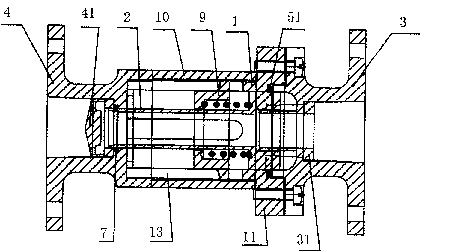
[0029] Such as figure 2 As shown, a pressure controller includes a valve body 1 and a valve core 2 disposed therein. Both ends of the valve body 1 are connected with an inlet valve section 4 and an outlet valve section 3, and an inlet valve section 4 and an outlet valve section 3 All are in the form of French blue plates. The valve body 1 is provided with a fixed seat 11, and the outlet valve section 3 is connected with the fixed seat 11 on the valve body 1 through bolts. The tail end of the valve body 1 is provided with threads, and the inlet valve section 4 is connected with the valve body 1 through threads. At one end of the outlet valve section 3, the valve body 1 and the valve core 2 are sealed by an O-ring 51, and this structure is applied to high pressure occasions. All the other are the same with embodiment 1.
PUM
 Abstract
Description
Claims
Application Information
 - R&D
- Intellectual Property
- Life Sciences
- Materials
- Tech Scout
- Unparalleled Data Quality
- Higher Quality Content
- 60% Fewer Hallucinations
Browse by: Latest US Patents, China's latest patents, Technical Efficacy Thesaurus, Application Domain, Technology Topic, Popular Technical Reports.
© 2025 PatSnap. All rights reserved.Legal|Privacy policy|Modern Slavery Act Transparency Statement|Sitemap|About US| Contact US: help@patsnap.com


