Vehicular flushing liquid closed cycle dirty oil and water treatment system for water injection well
A closed-circuit circulation and treatment system technology, applied in the direction of sterilization/microdynamic water/sewage treatment, etc., can solve the problems of substandard water quality of well cleaning fluid, low work efficiency, and inability to continuously circulate well for cleaning, and reduce well cleaning operations. Cost, reduce labor intensity, compact structure
- Summary
- Abstract
- Description
- Claims
- Application Information
AI Technical Summary
Problems solved by technology
Method used
Image
Examples
specific Embodiment approach 1
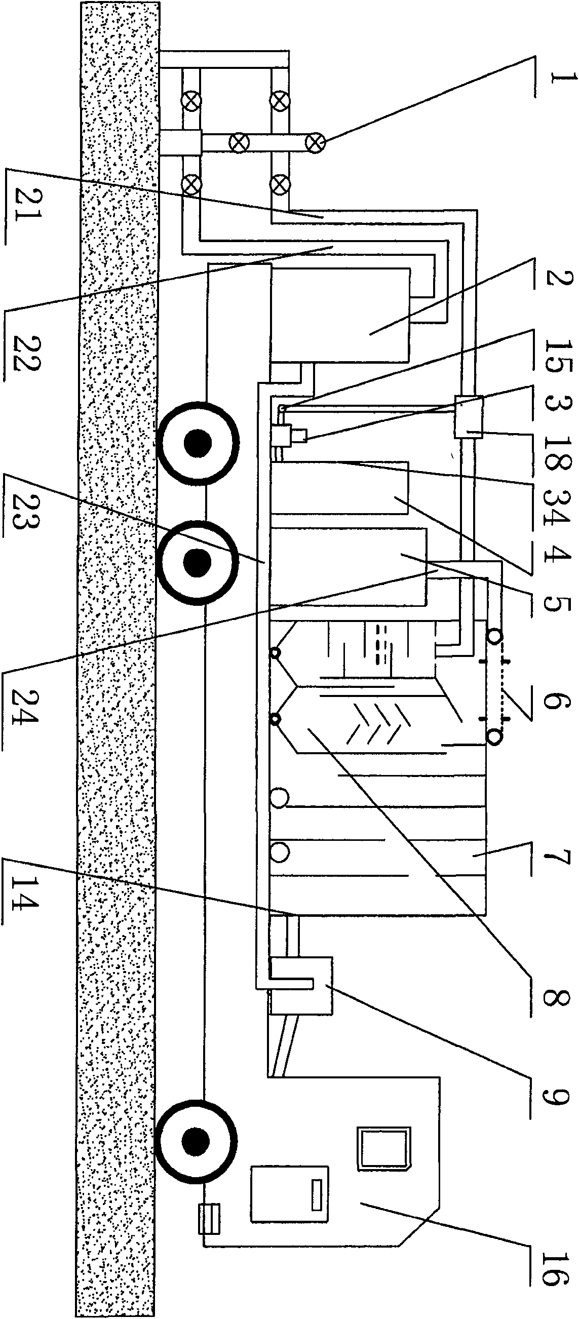
[0007] Specific implementation mode one: as figure 1 , figure 2 , Figure 4 As shown, the vehicle-mounted water injection well flushing fluid closed-circuit circulating dirty oil and water treatment system of the present embodiment comprises a car body 16, a dirty oil tank 5, a circulation pump 9, a shunt 15, a water turbine 18, a well flushing fluid return circulation pipe 21, Water injection pipe 22, well flushing fluid return pipe 23, sewage pipe 24, non-powered oil-water separator 7, drip dosing device 34, and fine filter device 2; well flushing fluid return circulation pipe 21 communicates with water turbine 18, and the outlet of water turbine 18 passes through The flow divider 15 communicates with the drip dosing device 34, the well flushing fluid return circulation pipe 21 communicates with the unpowered oil-water separator 7, the dirty oil tank 5 communicates with the unpowered oil-water separator 7 through the sewage pipe 24, and the unpowered oil-water separator 7 ...
specific Embodiment approach 2
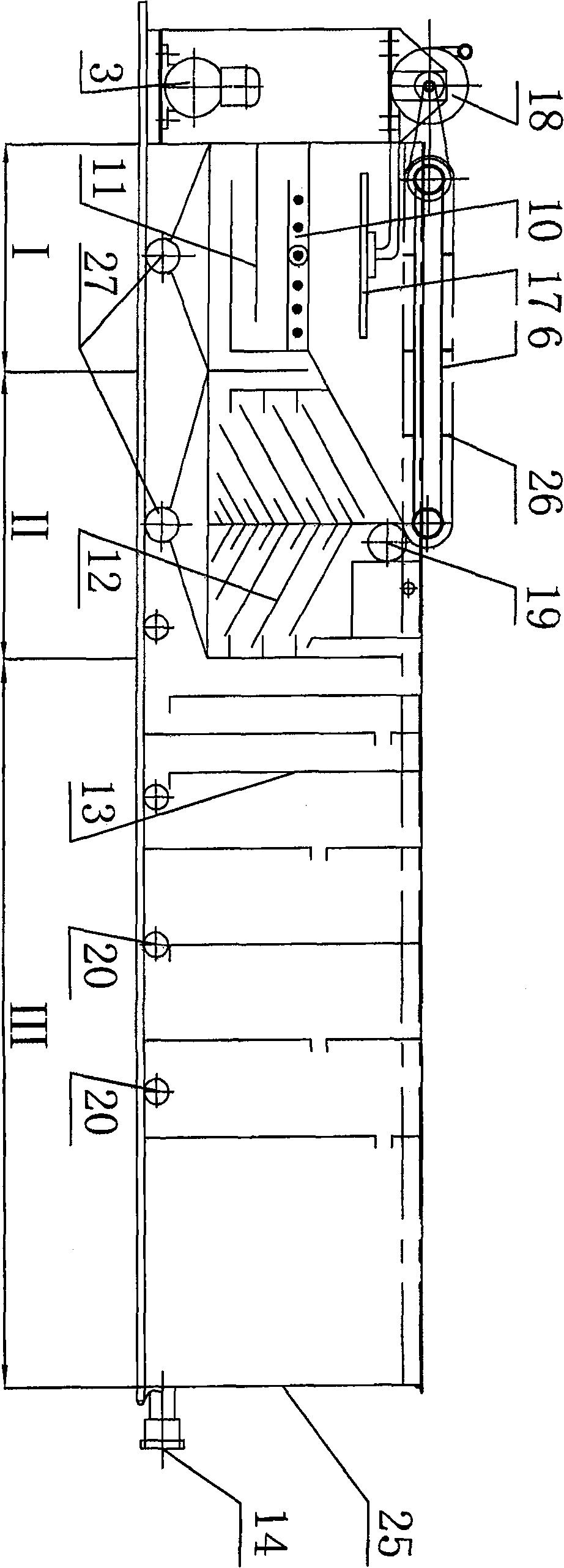
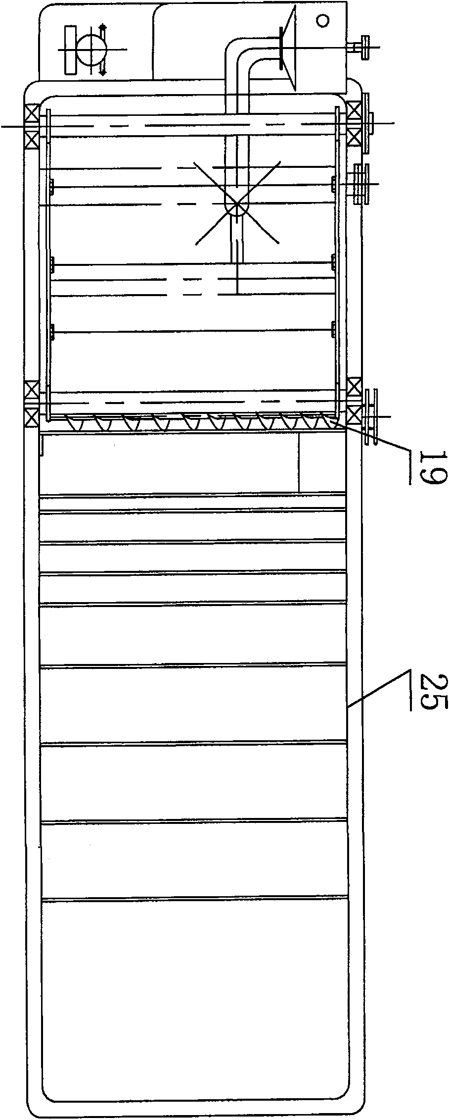
[0008] Specific implementation mode two: as figure 2 , image 3 As shown, the non-powered oil-water separator 7 described in this embodiment consists of an oil drainer 6, a shower 17, an air flotation device 10, a flow stabilization plate 11, a separation layer 12, a partition 13, a screw propeller 19 and The shell 25 is composed of the oil drainer 6 fixed on the left upper end of the shell 25, the sprayer 17 is arranged on the left upper part of the shell 25, the sprayer 17 is connected with the outlet of the water turbine 18, and the air flotation device 10 is arranged on the sprayer. Below the shower 17, the air flotation device 10 is provided with a stabilizing plate 11, the housing 25 on the right side of the stabilizing plate 11 is provided with a separation layer 12, and the screw propeller 19 is fixed on the lower right side of the oil drainer 6 On the housing 25, the housing 25 on the right side of the separation layer 12 is provided with a partition 13. With such ...
specific Embodiment approach 3
[0009] Specific implementation mode three: figure 2 As shown, the bottom of the side of the casing 25 in this embodiment is provided with a screw drainer 27 and a drain hole 20 . With such a structure, the dirt separated by sedimentation can be effectively discharged. Other components and connections are the same as those in the first embodiment.
[0010] Specific implementation mode four: as figure 2 As shown, the air flotation device 10 in this embodiment is a horizontal serpentine tube with holes. With such a structure, the suspended solids can rise and separate. Other components and connections are the same as those in the first embodiment.
PUM
 Abstract
Description
Claims
Application Information
 - R&D Engineer
- R&D Manager
- IP Professional
- Industry Leading Data Capabilities
- Powerful AI technology
- Patent DNA Extraction
Browse by: Latest US Patents, China's latest patents, Technical Efficacy Thesaurus, Application Domain, Technology Topic, Popular Technical Reports.
© 2024 PatSnap. All rights reserved.Legal|Privacy policy|Modern Slavery Act Transparency Statement|Sitemap|About US| Contact US: help@patsnap.com


