LED constant-flow driver

A constant current driver and current sampling technology, which is applied in the field of power circuits, can solve problems such as large heat generation, unadjustable frequency, and limited voltage division effect of current-limiting resistors, so as to prolong service life, reduce product cost, and consume less power consumption Effect

Inactive Publication Date: 2009-12-16
BEIJING LAMPEARL PHOTOELECTRIC
View PDF4 Cites 0 Cited by
  • Summary
  • Abstract
  • Description
  • Claims
  • Application Information

AI Technical Summary

Problems solved by technology

The current-limiting resistor only acts as a voltage divider, and it cannot generate a constant current. Even if the working current flowing through the LED is safe, the LED will still flicker with the change of current. The voltage effect is also limited. If the grid voltage rises too much, the working current of the LED will still exceed the safe value, thus burning the LED
At the same time, the current-limiting resistor itself consumes a lot of power and generates a lot of heat during work. The temperature is as high as 100 degrees Celsius. If the heat dissipation conditions are not good, it will easily cause safety accidents.
[0004] There are many deficiencies in the PWM technology using IC chips, mainly in: this kind of technology is only adjustable in pulse width but not in frequency, and because of the use of IC chips, the cost is high

Method used


Image

  • LED constant-flow driver
  • LED constant-flow driver

Examples


Embodiment Construction

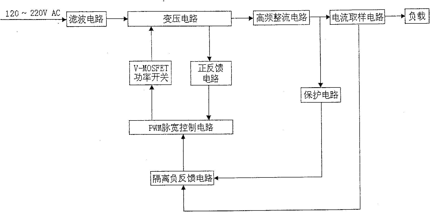
[0018] An LED constant current driver includes a filter circuit, a voltage transformer circuit, a high-frequency rectification filter circuit, a current sampling circuit, a protection circuit, an isolated negative feedback circuit, a positive feedback circuit, a PWM pulse width control circuit and a V-MOSFET power switch. The filter circuit includes an EMI filter and a rectifier filter, and the current limiting resistor R is passed between the EMI filter and the rectifier filter. 1 and negative temperature thermistor R 2 connect.

[0019] The current limiting resistor R in the filter circuit 1 The function is to fuse quickly when the latter stage is over-current, so as to prevent the driver from burning out.

[0020] Negative Temperature Thermistor R 2 The function is that when the ambient temperature rises, the resistance value rises, so that the output current amplitude of the driver decreases, and the power consumption of the load and the driver decreases.

[0021] The ...


PUM


Abstract

The invention discloses a drive in constant current for LED. Passing through circuits of filter, transformation, rectification filter in high frequency and electric current sampling circuit, electric signal is input to load. One input end of isolated negative feedback circuit receives signal outputted from an output end of the sampling circuit, and the other end receives inputted signal of protective circuit from the rectification filter circuit. One input end of PWM pulse width control circuit receives signal from negative feedback circuit, and the other end receives inputted signal of positive feedback circuit from the transformation circuit (TC). Through V-MOSFET power switch, signal output from the PWM controls TC. Combination between PWM and V-MOSFET power switch makes PWM produced pulse width adjustable. The invention also makes frequency be adjusted automatically when load is changed. Advantages are: constant working current, less power consumption, and low cost.

Description

technical field [0001] The invention belongs to the field of power circuits, and in particular relates to an LED constant current driver. Background technique [0002] LED is a new type of light source with energy saving, environmental protection and long life, but it has the following electrical characteristics, that is, a small change in the voltage applied to the LED will cause a large change in the current flowing through the LED, so if the current is not adjusted limit, the LED will be burned very easily. At present, the commonly used current limiting methods are LED series current limiting resistors and PWM technology using IC chips. [0003] There are many deficiencies in LED series current-limiting resistors, mainly manifested in: LED work is unstable. The current-limiting resistor only acts as a voltage divider, and it cannot generate a constant current. Even if the working current flowing through the LED is safe, the LED will still flicker with the change of curr...

Claims


Application Information

Patent Timeline
Patent Type & Authority Patents(China)
IPC IPC(8): H05B37/02H05B37/00
Inventor 梁辉妙钟金元
Owner BEIJING LAMPEARL PHOTOELECTRIC
Why Eureka
Try Eureka