Oil pumping workover rig

A workover rig and oil pumping technology, applied to drilling equipment, wellbore/well components, drill pipes, etc., can solve the problems of reduced service life and performance of equipment, insufficient traction, difficult workover, etc., to achieve workover function Integrity, prolonging service life and convenient workover

Inactive Publication Date: 2009-12-02
金成群
View PDF5 Cites 0 Cited by
  • Summary
  • Abstract
  • Description
  • Claims
  • Application Information

AI Technical Summary

Problems solved by technology

The hoisting sheave and hoisting rope used for workover of this structure of the well workover rig are far away from the center of the well, and the tubing is bent during the workover, and the traction force is not enough during the workover, so it is difficult to realize the workover. Well; only the high-speed end of the power transmission part is equipped with electric brakes, so when braking, each transmission part bears a huge impact, reducing the service life and performance of the equipment

Method used


Image

  • Oil pumping workover rig
  • Oil pumping workover rig
  • Oil pumping workover rig

Examples


Embodiment Construction

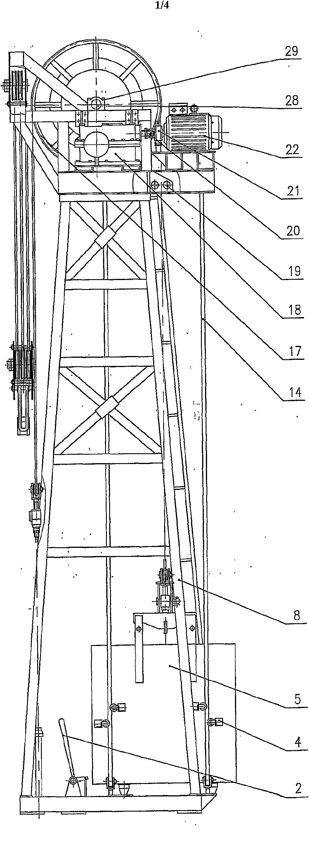
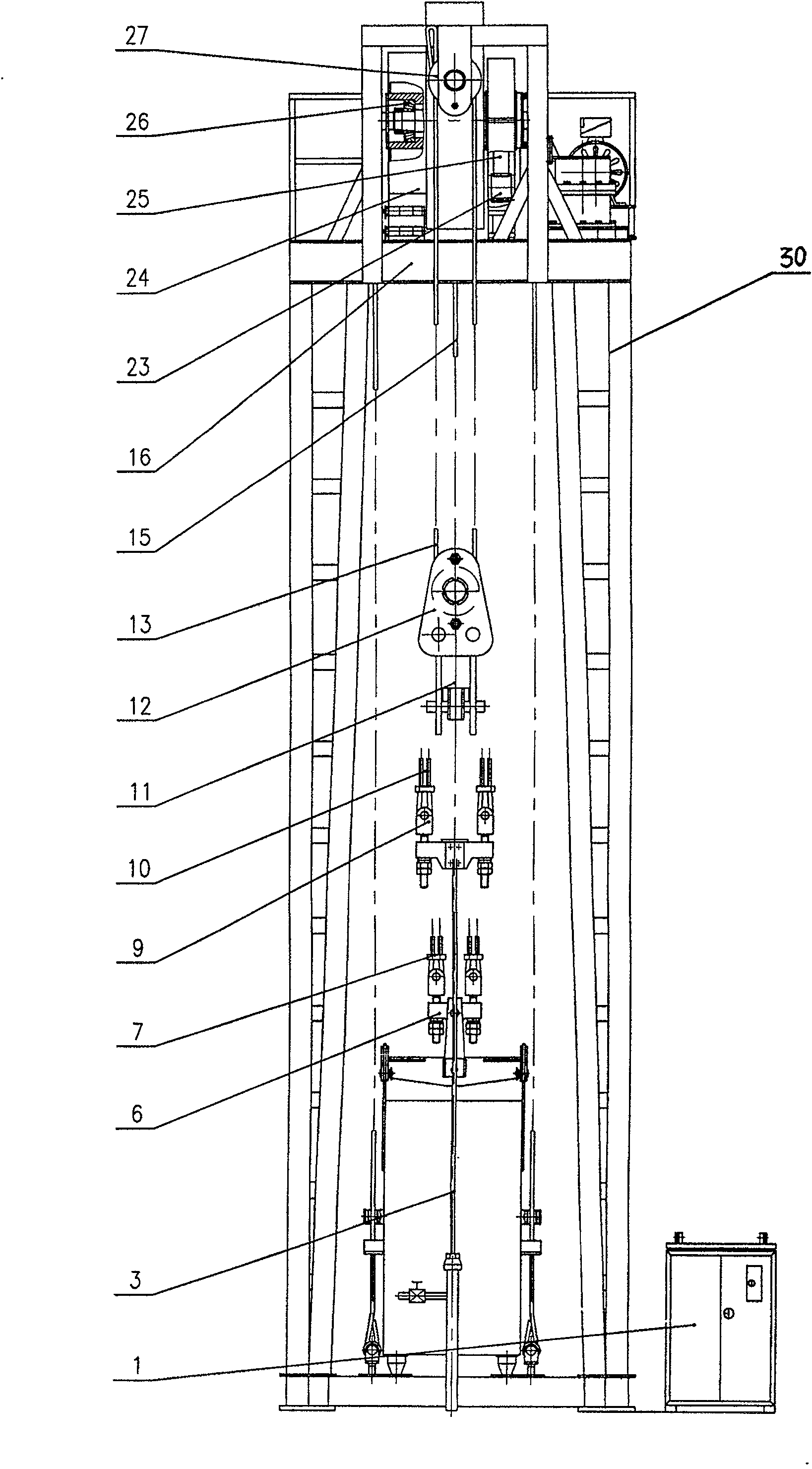
[0013] refer to figure 1 , figure 2 , the present invention includes an electric control cabinet 1, a main frame 8, a support platform 16, a motor 22, an electric brake 21, a coupling 20, a reducer 18, a polished oil rod 3, a rope suspension device 9 for a polished oil rod, and a sucker rod rope 10. Counterweight box 5, counterweight rope hanger 6, counterweight rope 7, protection rope 15, protection rope clamp 19, driving device, bracket platform 16 is located on the main frame 8, and motor 22 passes through electric brake 21 and joint The shaft device 20 is in drive connection with the reducer 18, the reducer 18 is connected to the driving device, one end of the sucker rod rope 10 is connected to the oil sucking rod 3 through the oil sucking rod hanging device 9, and the other end is fixed on the driving device, and one end of the counterweight rope 7 is Connect the counterweight rope hanger 6 on the counterweight box 5, and the other end is fixed on the driving device, an...


PUM


Abstract

The invention refers to a kind of oil pumping and well repairing machine, it includes electric control cabinet, main frame, bracket platform, electric motor, electric brake, shaft coupling, speed reducer, oil pumping smooth pole, rope suspending device, pumping rod rope, weight box, weight rope hanging device, weight rope, protecting rope, protecting rope clamp, driving unit. One end of the protecting rope is connected to the weight rope hanging device, and the other end is fixed on the driving unit. The driving unit and braked wheel positioned on an end of the driving unit form the driving brake. Fixed pulleys are provided on the bracket platform. An end of workover rope is fixed on the driving unit, the opposite end of the rope is rounded the fixed pulleys and travelling pulleys, then is fixed on the bracket platform. The lower end of the travelling pulleys is attached to an elevator. A braking handles positioned on the bottom of main frame is used for controlling the braked wheel. It is reliable and convenient.

Description

Technical field: [0001] The invention belongs to petroleum machinery, in particular to an oil pumping and workover machine capable of pumping oil and working over wells. Background technique: [0002] The oil pumping and workover rig with the patent number 200310100186.X is composed of a sky wheel shaft, a reducer, a large gear, a pinion gear, a motor, a hoisting rope of the sky wheel, a counterweight, a counterweight frame, a guide wire rope, an oil pumping polished rod, and a main frame , a bracket platform and a sky wheel, one end of the rope hanger is connected to the oil pumping rod, and the other end is connected to the wheel circumference of the sky wheel through the rope hanger traction rope, and the counterweight is passed through the counterweight frame, the rope hanger and the counterweight traction rope Fastened on the wheel circumference of the sky wheel, the motor is connected to the reducer through a brake and a coupling, the output shaft of the reducer is con...

Claims


Application Information

Patent Timeline
Patent Type & Authority Patents(China)
IPC IPC(8): E21B43/00
CPCE21B19/02E21B43/127
Inventor 金成群
Owner 金成群
Why Eureka
Try Eureka