
Magnetic-field-measuring device

A technology for measuring equipment and magnetic fields, which is applied in the direction of using electromagnetic devices for magnetic field measurement, measurement of electricity, measurement devices, etc., and can solve problems such as expensive equipment

Inactive Publication Date: 2009-11-18
CENT NAT DETUD SPATIALES (CNES)
View PDF5 Cites 0 Cited by
  • Summary
  • Abstract
  • Description
  • Claims
  • Application Information

AI Technical Summary

Problems solved by technology

[0009] Those are also very expensive due to the presence of spectrum analyzers and synchronous detectors

Method used


Image

  • Magnetic-field-measuring device
  • Magnetic-field-measuring device
  • Magnetic-field-measuring device

Examples


Embodiment Construction

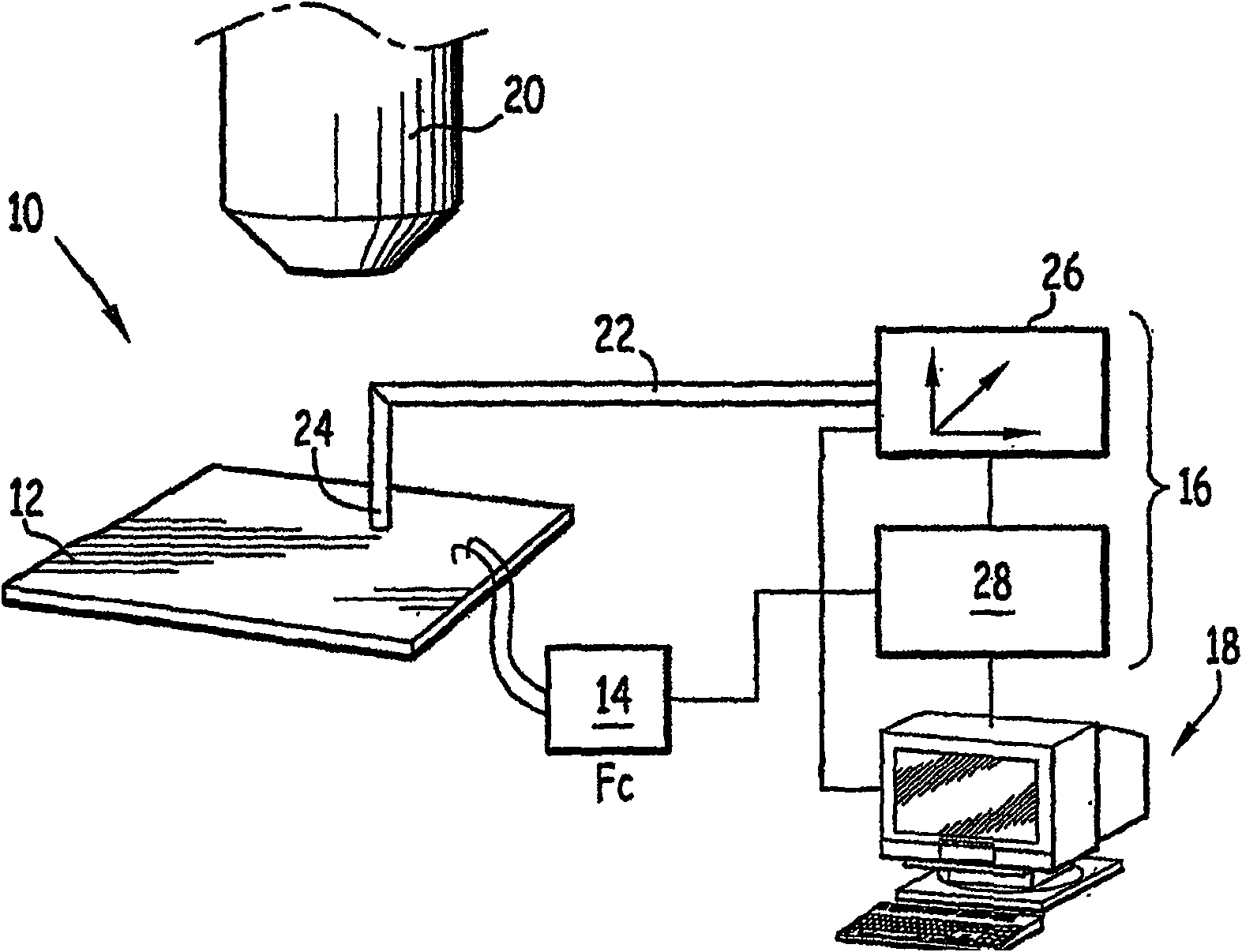
[0025] figure 1 The device shown is used to analyze a circuit in operation.

[0026] The device basically comprises a support plate 12 for the integrated circuit C, a circuit 14 for exciting the integrated circuit at a predetermined frequency FC, a device 16 for analyzing the magnetic field generated by the circuit C during operation, and a device for performing an analysis on the magnetic field The output of the device 16 is obtained by means 18 of the result. The device further comprises means 20 for viewing the integrated circuit during operation. Those means are known per se, so a detailed description thereof will be omitted.

[0027] The support 12 on which the circuit C is placed consists of a mu metal plate, or includes a mu metal plate at its lower portion away from the circuit, which forms a barrier to the magnetic field. Advantageously, the circuit C is confined within a mum box.

[0028] The excitation circuit 14 is formed, for example, by a frequency generator ...


PUM


Abstract

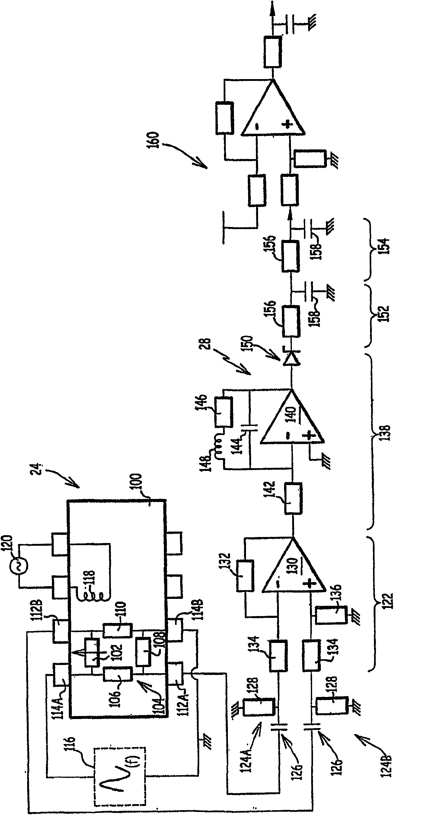
The invention relates to a device (16) for measuring at least one component of a magnetic field. The device of the invention includes a magnetoresistive sensor (102) and a measuring chain (28). According to the invention, the input of the aforementioned measurement chain is connected to the magnetoresistive sensor (102), while its output is used to provide information representative of the magnetic field in the sensor area. Furthermore, the measurement chain (28) includes means (136) for isolating frequency components of the signal from the sensor that represent the magnetic field for a single predetermined frequency (FI).

Description

technical field [0001] The invention relates to a device for measuring magnetic fields, a device of this type comprising a magneto-resistive or magneto-inductive sensor and a measuring chain to which the input is connected, the output of which is able to provide a representative sensor area Information about the magnetic field inside. Background technique [0002] In order to control integrated circuits or to measure the radiation generated by the circuit during operation, it is known to arrange one or more sensors above the circuit in order to determine the magnetic or electric fields generated by the operation of the circuit. To detect magnetic fields, these devices use antennas or "SQUIDS," or superconducting quantum interference devices. [0003] More recently, it has been envisaged to use magnetoresistive sensors, more precisely GMR type sensors (giant magnetoresistive sensors) to measure the magnetic field generated by the circuit during operation. [0004] This type...

Claims


Application Information

Patent Timeline
Patent Type & Authority Patents(China)
IPC IPC(8): G01R31/00G01R33/09G01R31/302G01R33/02G01R33/06
CPCG01R31/002G01R33/02G01R33/09
Inventor 罗迈因·德斯朴拉特斯奥利弗·卡里普尔菲利克斯·博杜安菲利普·佩尔都
Owner CENT NAT DETUD SPATIALES (CNES)
Learn More