Signal precoding method

A precoding and signal technology, applied in the field of signal precoding, can solve the problems of large matrix H, degraded signal detection performance, degraded system performance, etc., so as to reduce the probability of singularity, improve signal detection performance, and improve work performance.

Inactive Publication Date: 2009-10-21
POTEVIO INFORMATION TECH CO LTD
View PDF7 Cites 0 Cited by
  • Summary
  • Abstract
  • Description
  • Claims
  • Application Information

AI Technical Summary

Problems solved by technology

[0019] For the convenience of illustration, here it is assumed that h 11 , h 12 , h 21 , h 22 They are all 1. If there is no special explanation below, this assumption is established. It is obvious that H H H, is a singular matrix, if it cannot be solved, the weighting factor cannot be obtained, and then the transmitted signal d cannot be estimated correctly, which will seriously reduce the performance of the system
In a MIMO system, when the channel is a Gaussian channel or the correlation between the branches of the channel is strong, the matrix H H H is more likely to be singular, and in severe cases, it will cause the MIMO system to fail to detect signals normally
[0020] In fact, for other signal detection algorithms, the inversion process of a certain matrix may also be involved in the process of signal detection. If the matrix is ​​singular, the problem of signal detection performance degradation will occur.

Method used


Image

  • Signal precoding method
  • Signal precoding method
  • Signal precoding method

Examples


Embodiment

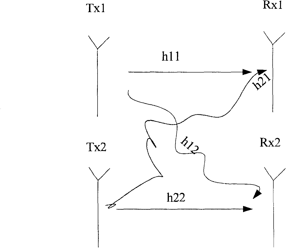
[0054] In this example, it is assumed that figure 1 The MIMO system shown is further a TD-SCDMA system, and its uplink and downlink traffic channels are symmetrical, so the channel matrix can be obtained.

[0055] This embodiment continues to use the received signal model shown in formula (6), and simplifies it to

[0056] y 11 y 12 y 21 y 22 = h 11 h 21 h ...


PUM


Abstract

The invention discloses a signal precoding method, which is characterized in that the method includes: delaying the signals on each transmitting antenna; performing phase weighting on each delayed signal. After the signal processed by the above precoding process reaches the receiving end, when detecting the original signal, it is necessary to eliminate the weighted phase and delay time, which is equivalent to modifying the channel matrix. In this way, in the subsequent detection process, the singular inversion matrix that will appear according to the original channel matrix will no longer be singular at this time, thus greatly improving the signal detection performance of the system.

Description

technical field [0001] The invention relates to the signal transmission technology of the mobile communication system, in particular to a signal precoding method. Background technique [0002] In the mobile communication system, the sending end sends various signals. After the signal reaches the receiving end through the wireless channel, some changes may occur. The receiving end uses a certain algorithm to restore the received signal to the sending signal process, which is called Signal Detection. [0003] Suppose the signal received by the receiver is Y=Hd+n (1) [0004] Among them, A is the channel matrix, indicating the channel characteristics of the transmitted signal during transmission, d is the transmitted signal, indicating the actual information of the transmitting end, and n is the channel noise. When the receiving end performs signal detection, the usual method is: first obtain the weighting factor W, and then estimate the transmitted signal according to Y=Wd. ...

Claims


Application Information

Patent Timeline
Patent Type & Authority Patents(China)
IPC IPC(8): H04L1/00H04L1/06
Inventor 程型清
Owner POTEVIO INFORMATION TECH CO LTD
Why Eureka
Try Eureka