Eureka AIR delivers breakthrough ideas for toughest innovation challenges, trusted by R&D personnel around the world.

Optical fibre grating digital demodulation method and system based on autocorrelation principle

A technology of fiber grating and demodulation method, which is applied in the coupling of optical waveguide and the transmission of sensing components by optical devices, etc., which can solve the problem of low measurement accuracy and high price of fiber grating sensing system demodulation technology, which cannot meet the actual needs of the project And other issues

Inactive Publication Date: 2009-09-16
李东升
View PDF6 Cites 0 Cited by
  • Summary
  • Abstract
  • Description
  • Claims
  • Application Information

AI Technical Summary

Problems solved by technology

[0016] The purpose of the present invention is to solve the problems of low measurement accuracy, poor real-time performance, insufficient multiplexing ability, high price, and inability to meet the actual needs of engineering in the demodulation technology of the current fiber grating sensing system, and to provide a high measurement accuracy and fast scanning speed. , good real-time performance, strong multiplexing ability, high cost performance, and strong versatility. The fiber grating digital demodulation method and system based on the principle of autocorrelation

Method used

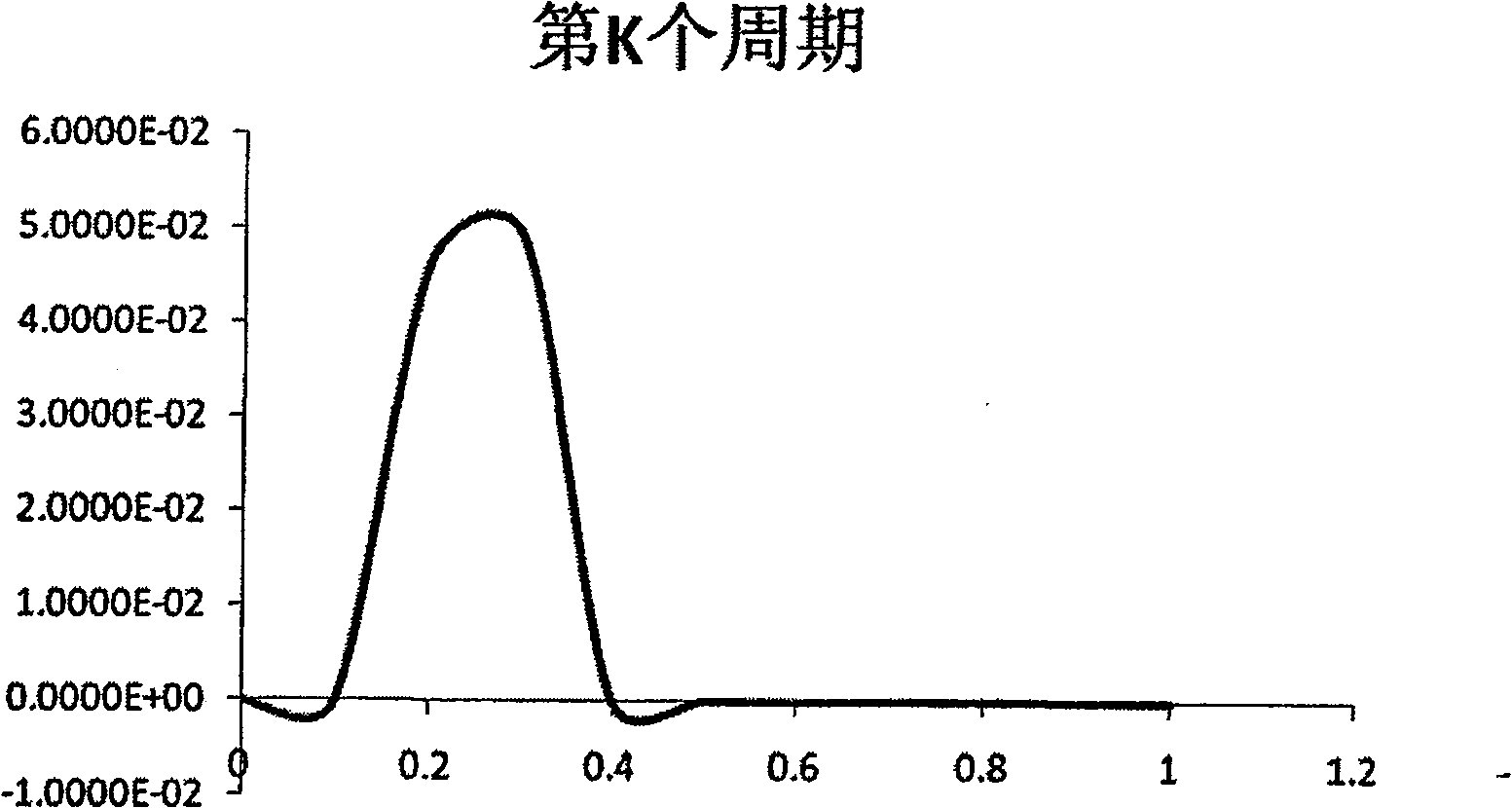

Image

  • Optical fibre grating digital demodulation method and system based on autocorrelation principle
  • Optical fibre grating digital demodulation method and system based on autocorrelation principle
  • Optical fibre grating digital demodulation method and system based on autocorrelation principle

Examples


Embodiment Construction

[0069] The present invention will be further described below in conjunction with the drawings and embodiments.

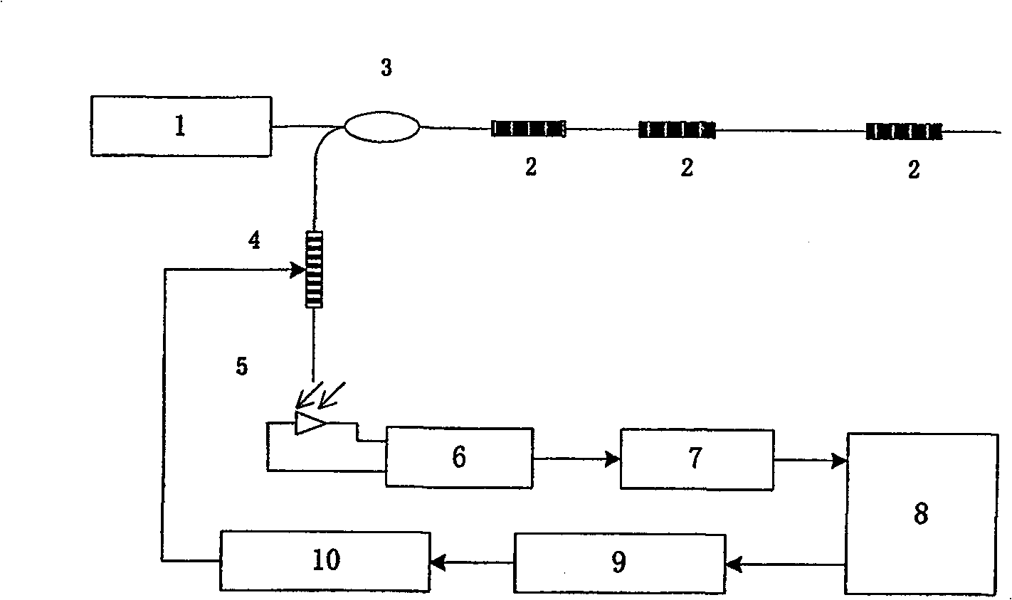
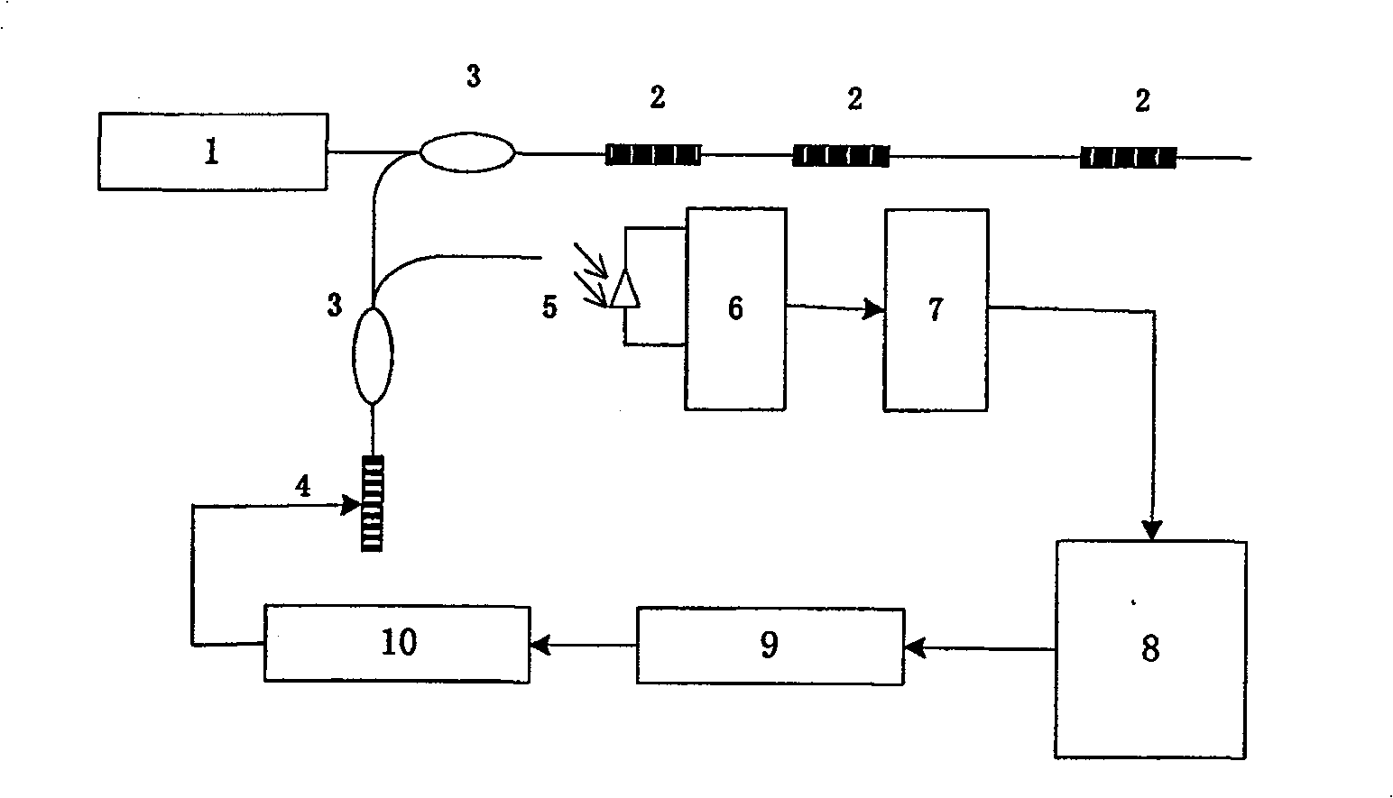
[0070] figure 1 , figure 2 In, the fiber grating autocorrelation digital demodulation system includes a broadband light source 1 and a number of serially connected fiber grating sensors 2. The light source 1 is connected to the fiber grating sensor 2 through a 2×2 coupler 3, and the coupling device is also connected to a tunable The filter 4 is connected, and the tunable filter 4 is connected to the photodetector 5. The photodetector 5 is connected to the preamplifier 6, the digital-to-analog converter 7, and the digital-to-analog converter 7 is connected to the digital controller 8 using the DSP chip. The input terminal is connected; the output terminal of the digital controller 8 is connected to the control input terminal of the tunable filter 4 via the electromechanical controller 9 and the electromechanical modulation system 10 in turn. The tunable filter 4 can b...


PUM


Abstract

The invention discloses a fiber grating digital demodulation method and system based on the principle of autocorrelation. It solves the problems of low measurement accuracy, poor real-time performance, insufficient multiplexing capability, high price, and inability to meet the actual needs of projects in the current fiber grating sensing system demodulation technology. It has high measurement accuracy, fast scanning speed, good real-time performance, and multiplexing Strong ability, high cost performance, and strong versatility. Its system is composed of: it includes a light source and at least one fiber grating sensor, the light source is connected to the fiber grating sensor in series through a coupling device, and the coupling device is also connected to a tunable filter, and the tunable filter is connected to the photodetector The photodetector is connected to the preamplifier and the digital-to-analog converter in turn, and the digital-to-analog converter is connected to the input of the digital controller; the output of the digital controller is sequentially passed through the electromechanical controller, the electromechanical modulation system and the tunable filter. connected to the control input of the device.

Description

Technical field [0001] The invention relates to a fiber grating digital demodulation method and system based on the autocorrelation principle. Background technique [0002] Fiber grating sensor is a kind of wavelength modulation device with compact structure and strong anti-interference ability. It is convenient to use multiplexing (wavelength division, time division, space division) technology to form a fiber optic sensor network for large-area multi-point measurement. Many fields such as machinery, medical care, aerospace, navigation, and mining have broad application prospects and have been greatly developed in recent years. [0003] At present, the theoretical research on fiber grating sensing has made great achievements, and the mature fiber grating manufacturing technology has also enabled the fiber grating sensor to have small batch production capacity. How to reduce costs, improve demodulation and multiplexing technology, and meet the requirements of engineering The requi...

Claims


Application Information

Patent Timeline
Patent Type & Authority Patents(China)
IPC IPC(8): G01D5/26G01D5/353G01D5/38G02B6/34
Inventor 李东升
Owner 李东升
Why Eureka
Eureka Blog
Learn More