
Asphalt felt spreader

A technology for pasting machines and linoleum, which is applied to roads, road repairs, roads, etc., can solve the problems of poor paste uniformity and effect, high labor intensity of construction personnel, and unsatisfactory construction, so as to achieve strong adhesion and good paste. The effect of high efficiency and compact structure

Inactive Publication Date: 2009-09-16
HENAN GAOYUAN ROAD MAINTENANCE EQUIP
View PDF3 Cites 0 Cited by
  • Summary
  • Abstract
  • Description
  • Claims
  • Application Information

AI Technical Summary

Problems solved by technology

Due to the long cement concrete pavement, the amount of linoleum laid is large, the labor intensity of the construction personnel is high, the efficiency is low, the construction period is long, and the uniformity and effect of the paste are poor, which cannot meet the technical requirements of construction.
At present, there is no equipment for pasting linoleum on the market. In order to reduce labor intensity, improve work efficiency, and ensure construction quality, there is an urgent need to develop and research mechanized construction equipment for laying linoleum on cement concrete roads.

Method used


Image

  • Asphalt felt spreader
  • Asphalt felt spreader
  • Asphalt felt spreader

Examples


Embodiment 1

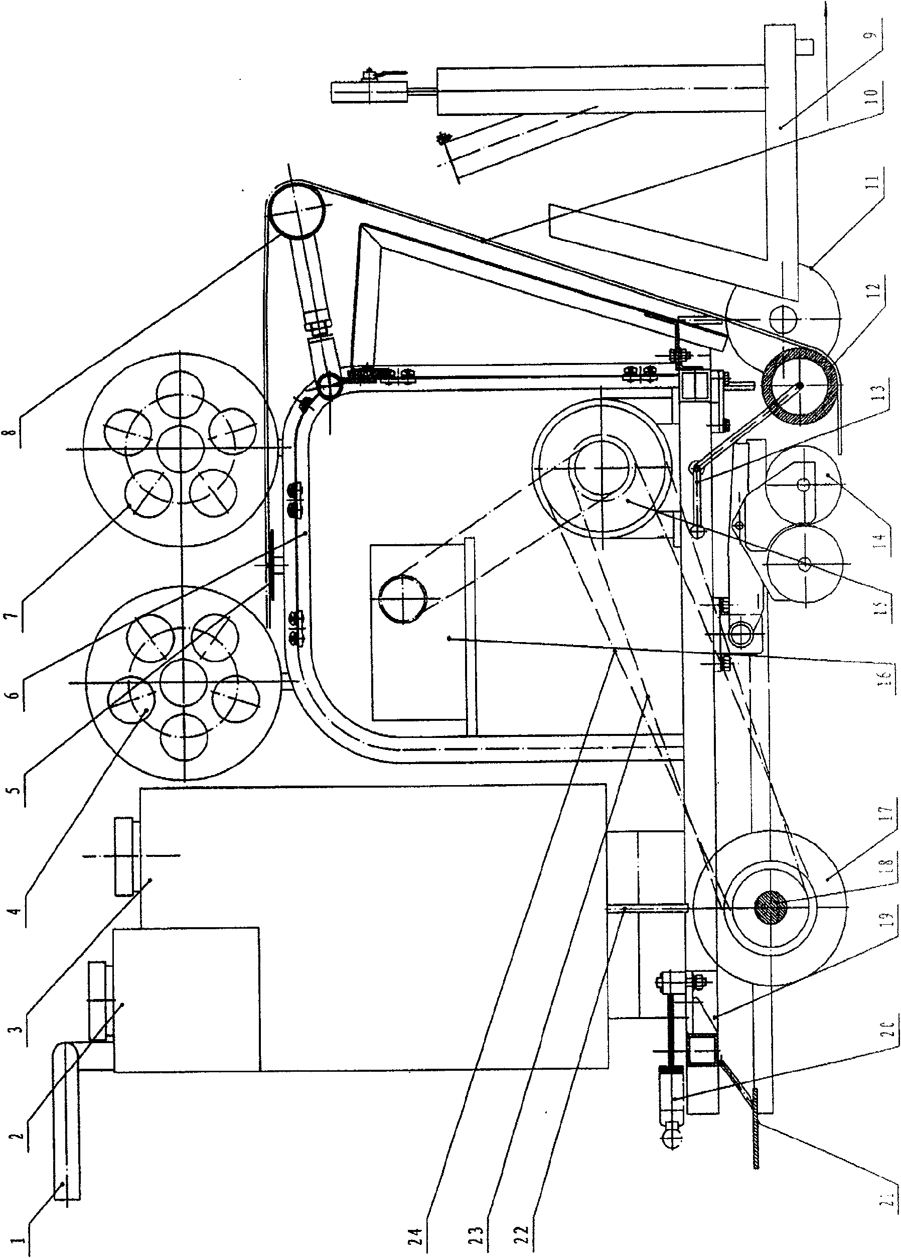
[0020] in figure 1 , 6 In this implementation, the felt applicator consists of the operating handle 1, the fuel tank 2, the water tank 3, the rear delivery felt roller 4, the felt connector 5, the frame 6, the front delivery felt roller 7, the felt guide roller 8, and the burner 9. , Front traveling wheel 11, front rolling felt roll 12, front pressure roller tie rod 13, rear rolling felt roll 14, reducer 15, engine 16, rear traveling wheel 17, axle 18, base 19, clutch 20, rear rolling The wheel control rod 21, the drip tube 22, the low-speed sprocket chain mechanism 23, and the fast sprocket chain mechanism 24 are connected together.

[0021] On the base 19, a combustor 9 is fixedly connected and installed with a screw fastening coupling at the front end, and a clutch 20 is fixedly connected and installed with a screw fastening coupling at the rear end. Between the burner 9 and the clutch 20 on the base 19, the frame 6, the engine 16, the reducer 15, the water tank 3, the rear ro...

Embodiment 2

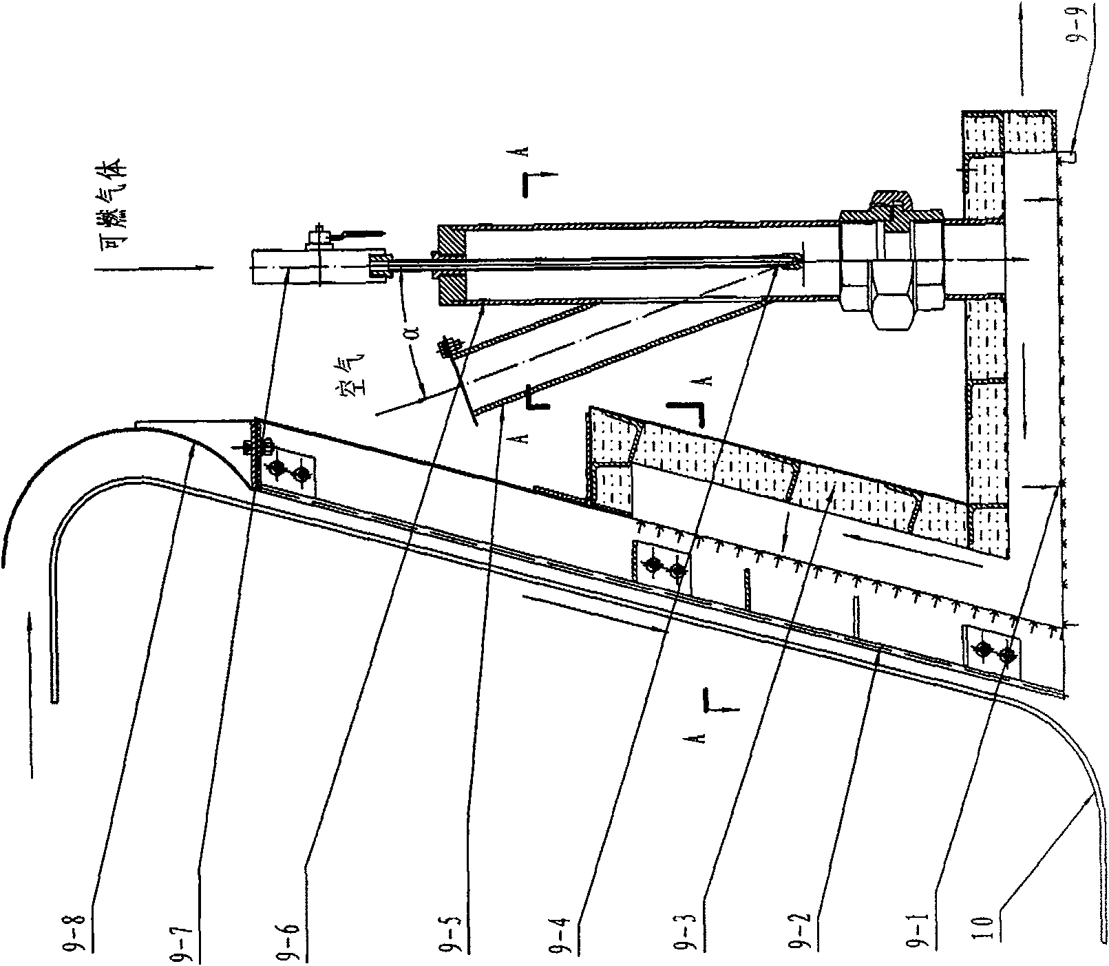
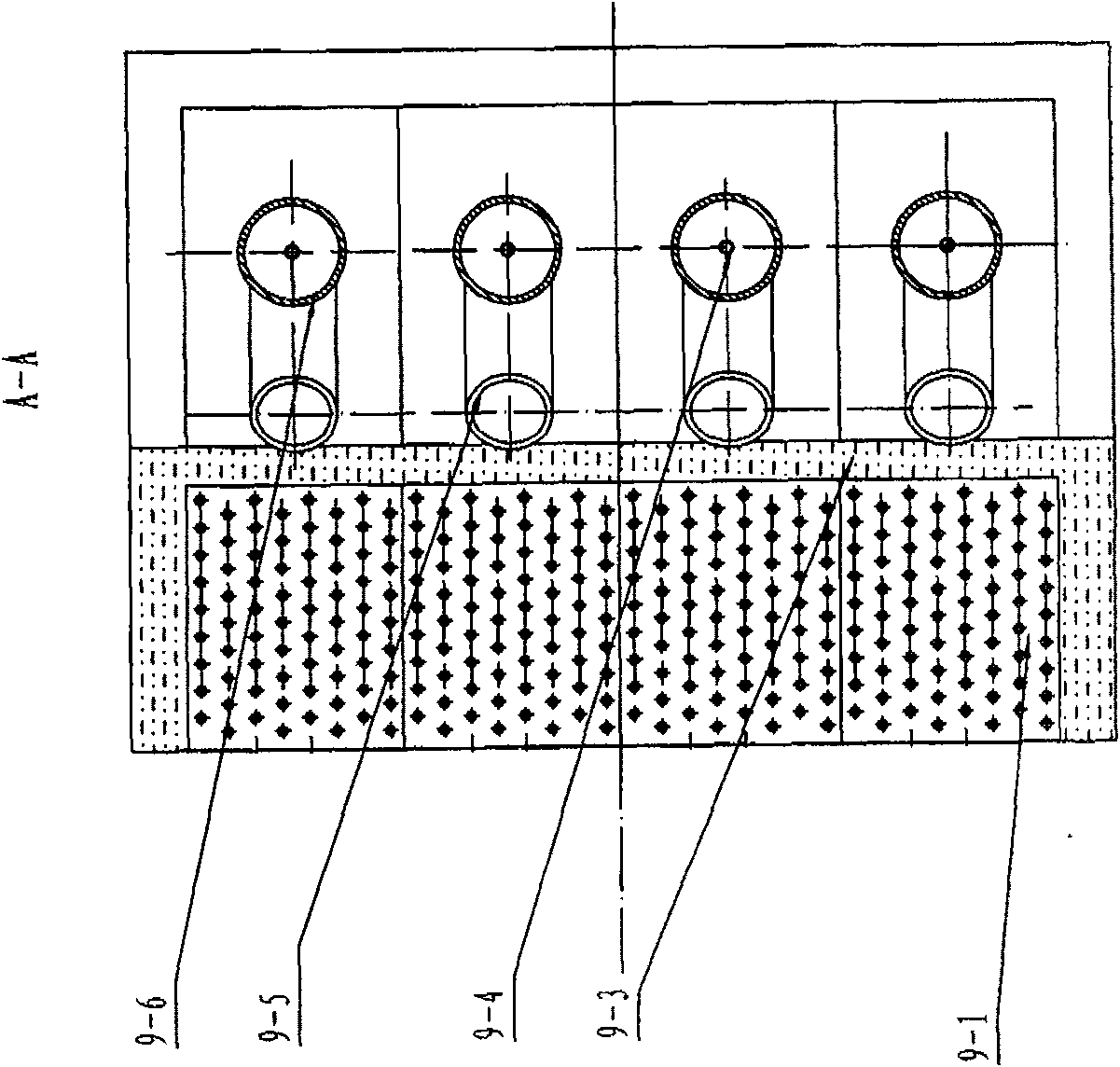
[0027] In this embodiment, the combined combustion chamber 9-1 is composed of 4 combustion chambers with exactly the same structure arranged in a row in the left and right direction. The combined combustion chamber 9-1 is equipped with 4 main mixing tubes 9-6, each of which is The pipe 9-6 communicates with a combustion chamber, and the side wall of each main mixing pipe 9-6 is fixedly connected with a threaded fastening connector to install an air suction pipe 9-5, which is connected to the main mixing pipe. 9-6 are connected, the angle α between the center line of the main mixing pipe 9-6 and the center line of the air suction pipe 9-5 is 10°, and the upper end of each main mixing pipe 9-6 is equipped with a gas control valve 9-7 , Each main mixing pipe 9-6 is equipped with a gas nozzle 9-4 connected with the gas control valve 9-7, and the gas nozzle 9-4 is located at the center line of the main mixing pipe 9-6 and the center of the air suction pipe 9-5 55mm below the line inter...

Embodiment 3

[0029] In this embodiment, the combined combustion chamber 9-1 is composed of 4 combustion chambers with exactly the same structure arranged in a row in the left and right direction. The combined combustion chamber 9-1 is equipped with 4 main mixing tubes 9-6, each of which is The pipe 9-6 communicates with a combustion chamber, and the side wall of each main mixing pipe 9-6 is fixedly connected with a threaded fastening connector to install an air suction pipe 9-5, which is connected to the main mixing pipe. 9-6 are connected, the angle α between the center line of the main mixing pipe 9-6 and the center line of the air suction pipe 9-5 is 20°, and the upper end of each main mixing pipe 9-6 is equipped with a gas control valve 9-7 , Each main mixing pipe 9-6 is equipped with a gas nozzle 9-4 connected with the gas control valve 9-7, and the gas nozzle 9-4 is located at the center line of the main mixing pipe 9-6 and the center of the air suction pipe 9-5 80mm below the line inter...


PUM


Abstract

A kind of linoleum laying machine, the front end of the base is provided with a burner, the rear end is provided with a clutch, and the base is provided with a frame between the burner and the clutch, an engine connected with a reducer, a water tank, a rear rolling wheel control rod, a front Pressure roller pull rod, the upper end of the water tank is provided with a fuel tank connected to the engine through a conduit, the fuel tank is provided with an operating handle, and the base is provided with 2 axles, a felt front roller connected with the front pressure roller pull rod, 1 or 2 with The back rolling wheel is connected to the linoleum rear rolling roller with the control lever. The front wheel shaft is equipped with 2 front travel wheels, and the rear wheel shaft is equipped with 1 rear wheel. The middle part of the rear travel wheel is equipped with a fast sprocket chain connected with the output shaft of the reducer. Mechanism, low-speed sprocket chain mechanism, water tank, burner and base are provided with drip pipes, and linoleum connectors, linoleum guide rollers and at least one linoleum delivery roller are arranged on the frame. The invention can be used for paving cracks on the cement concrete pavement before the cement concrete pavement is rebuilt into an asphalt concrete pavement, and can also be used for paving linoleum on the roof of a building.

Description

Technical field [0001] The invention belongs to the technical field of devices and equipment for repairing completed pavements, and specifically relates to a device or device for sticking linoleum on cement concrete pavements or cement concrete buildings. Background technique [0002] A large number of cement concrete pavements were built in China in the 1980s and 1990s. After years of operation, many pavements have successively appeared slab bottom voids, mud, broken slabs, dislocations, and subsidence. At present, the old cement concrete pavement has been damaged. The most effective way to repair, the professional and technical personnel in this technical field believe that the most effective solution is to pave a thin layer of asphalt concrete overlay on the cement concrete pavement, that is, the "white and black" pavement, but the "white and black" pavement has "reflection cracks". In order to overcome this disadvantage, it is necessary to add a stress absorbing layer, take m...

Claims


Application Information

Patent Timeline
Patent Type & Authority Patents(China)
IPC IPC(8): E01C23/06
Inventor 王选仓刘廷国何涛陈在旭
Owner HENAN GAOYUAN ROAD MAINTENANCE EQUIP
Learn More