Method and construction for preventing water leakage in diaphragm type compression pump

A pressure pump and diaphragm technology, applied in the field of pressure pumps, can solve the problems of inability to completely seal, loss of pressure, and reduced boosting efficiency.

Active Publication Date: 2009-09-09
蔡应麟 +1
View PDF20 Cites 1 Cited by
  • Summary
  • Abstract
  • Description
  • Claims
  • Application Information

AI Technical Summary

Problems solved by technology

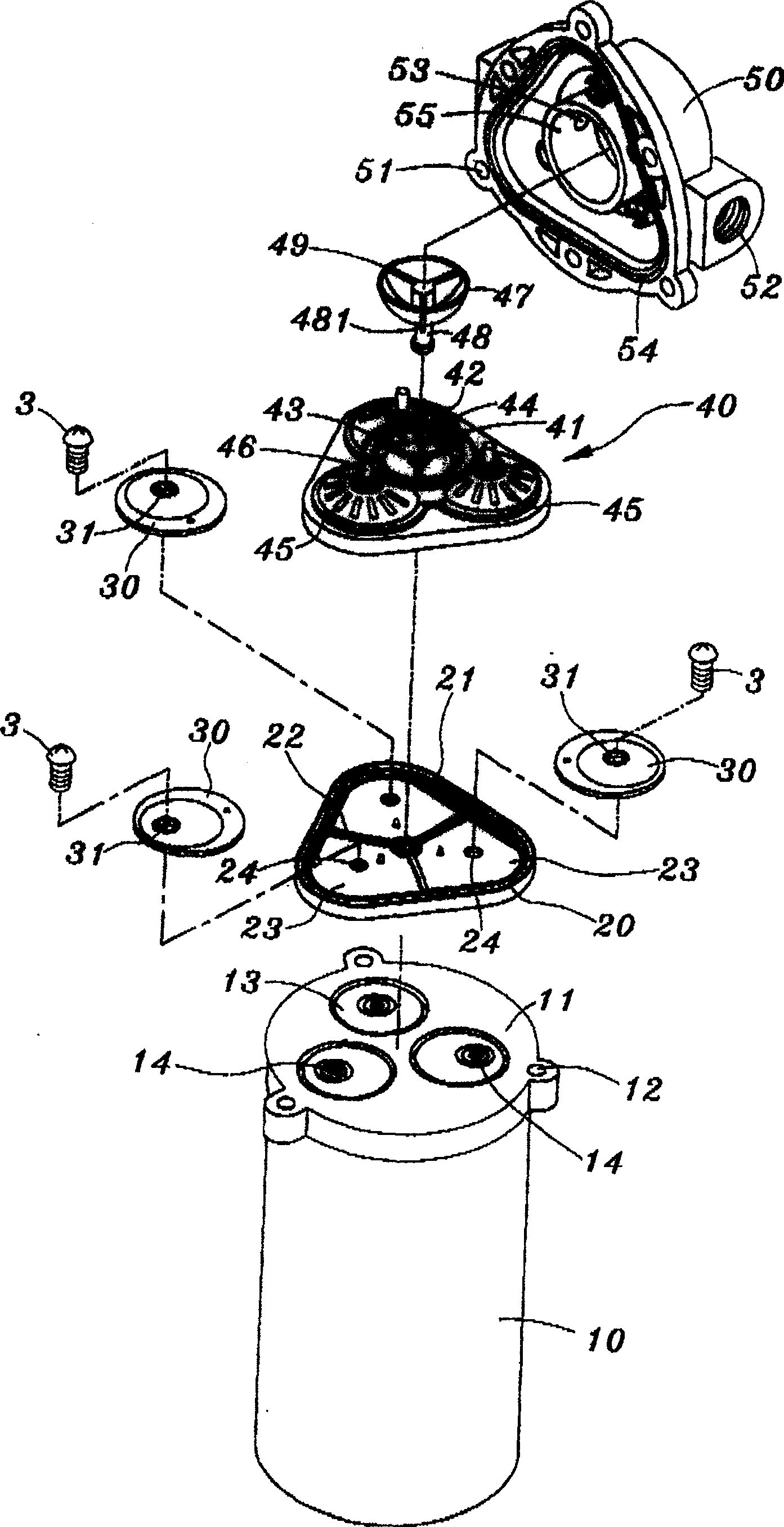
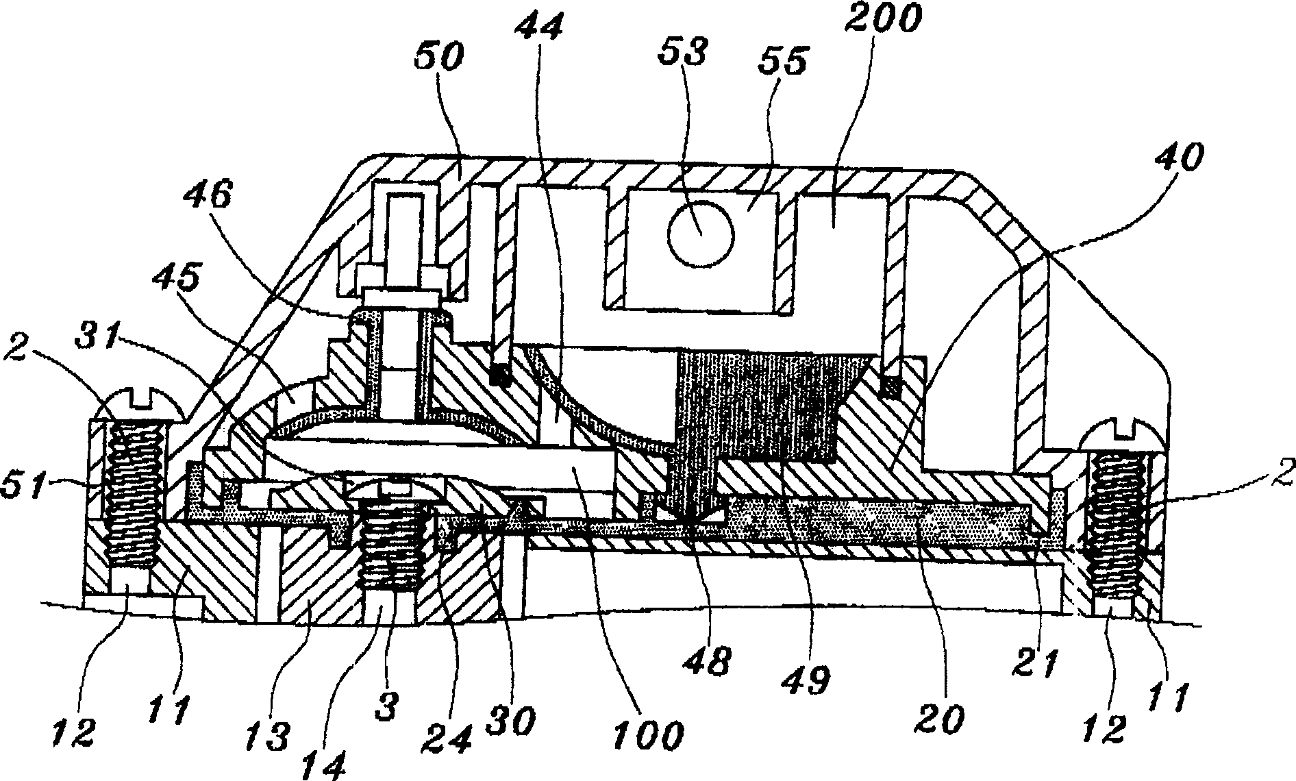
[0007] All the various conventional diaphragm pressure pumps disclosed above all have a serious deficiency, such as Figure 6 to Figure 9 As shown, when the motor 10 is started to pressurize, the balance wheels 13 are in contact with the diaphragm 20, so when the balance wheel 13 swings and pushes forward each time, the piston of the diaphragm 20 works in conjunction with each other. When the moving zone 23 is actuated, the diaphragm 20, which is clamped between the piston push block 30 and the balance wheel 13, will be stretched once (such as Figure 8 (shown by the imaginary line in the center), if the rotational speed of the motor 10 is 700 revolutions per minute (700rpm), then the diaphragm 20 will be stretched 700 times per minute, in such a high-frequency stretching action and use After a period of time, the diaphragm 20 at the piston action area 23 will gradually form a result that cannot be completely sealed with the bottom surface of the piston push block 30 due to the pulling. Figure 9 As shown), the high-pressure water Wp leaks into the output shaft of the motor 10 through the gap between the fixing screw 3 and the threaded hole 14 of the balance wheel 13, and finally causes the electric circuit of the motor 10 to be short-circuited, so that the entire diaphragm pressure pump The damage cannot be used. This major problem has not been solved in the manufacturing industry so far. Consumers can only gamble and spend the same price but may not get the same service life. If the motor 10 due to leakage There is also a risk of fire when there is water leakage and short circuit and burnt down
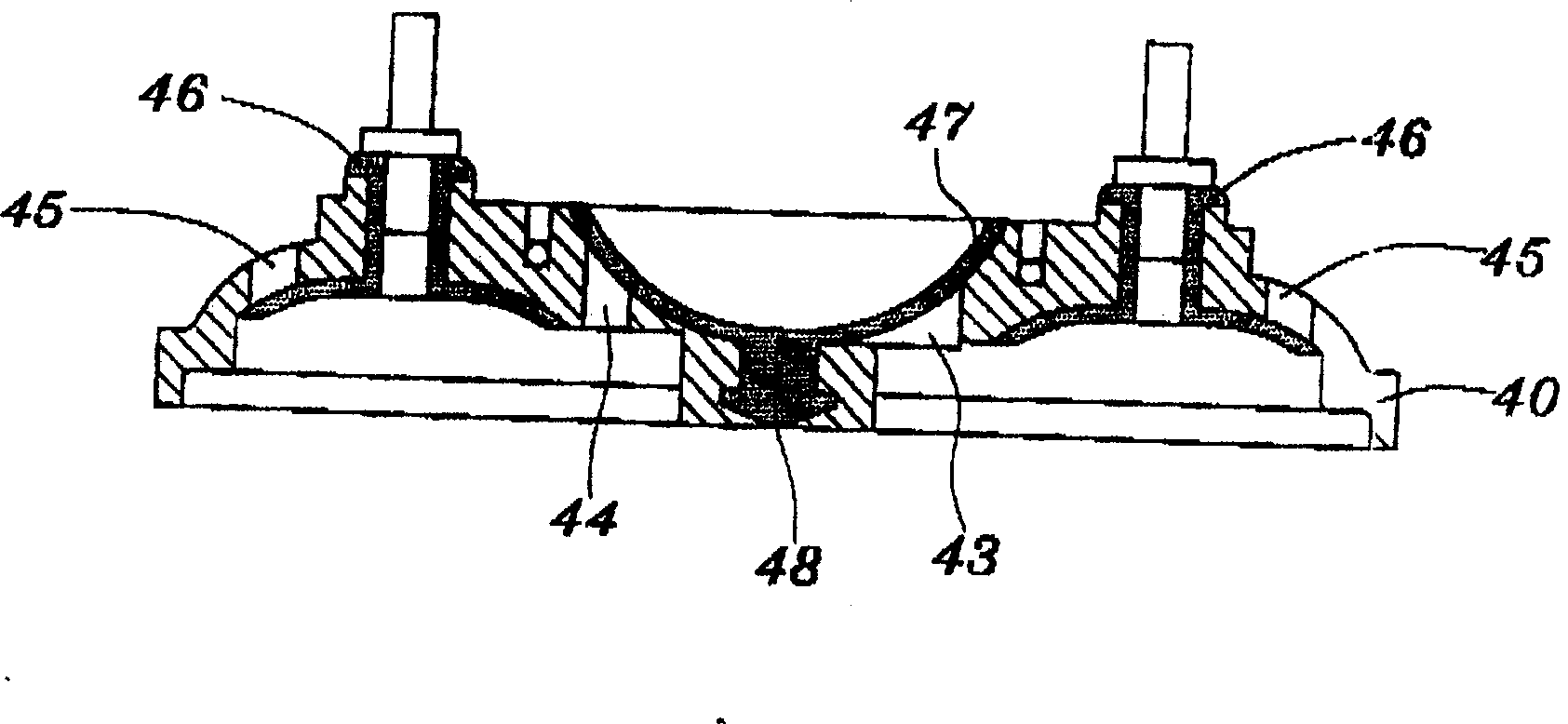
[0008] Furthermore, in addition to the above-mentioned major deficiency, another water leakage location that often occurs is between the pump head cover body 50 and the piston valve body 40, such as Figure 10 As shown, when the piston action area 23 of the diaphragm 20 is constantly pressed and moved by the balance wheel 13, the top surface of the outer peripheral edge of the piston valve body 40 also continuously hits the wall surface of the stepped groove 54 of the pump head cover body 50 ( like Figure 10 (shown by the black arrow in ), or pulling away from the contact between the two, since the piston valve body 40 and the pump head cover body 50 are both rigid bodies, there is no buffer structure design between the two, after repeated mutual After hitting and pulling away for a period of time, a gap is likely to occur, and under the action of water pressure, water will leak from the wall surface of the stepped groove 54 of the pump head cover body 50 and the outer peripheral top surface of the piston valve body 40 Out of the diaphragm pressure pump, it also indirectly forms a local pressure loss phenomenon, which in turn leads to a reduction in the overall boosting effect

Method used


Image

  • Method and construction for preventing water leakage in diaphragm type compression pump
  • Method and construction for preventing water leakage in diaphragm type compression pump
  • Method and construction for preventing water leakage in diaphragm type compression pump

Examples


Embodiment Construction

[0061] like Figure 11 to Figure 13 As shown, the method and structure thereof for preventing water leakage in a diaphragm pressure pump of the present invention is to first set a hollow cylinder 64 at the position of the screw hole on the top surface of each piston action area 63 of the diaphragm 60, And the hollow cylinder 64 and the diaphragm 60 are all integrally injection-molded with plastic materials having the same elasticity (such as Figure 11 And Figure 12 As shown in A view), and its outer diameter is equal to or slightly smaller than the inner diameter of the stepped hole 31 in the piston push block 30, and then the stepped hole 31 of the piston push block 30 is placed on the outer edge of the hollow cylinder 64 (such as Figure 12 After being shown in the view of B in the center), the central hole of the hollow cylinder 64 is passed through the set screw 3 (as shown in Figure 12 As shown in the view in C), and apply force to lock the fixing screw 3 into the th...


PUM


Abstract

The invention relates to a method and structure for preventing leakage of water in a diaphragm pressure pump. In the diaphragm of the diaphragm pressure pump, the positions of the screw holes corresponding to the balance wheels on each piston action area are respectively Set up a hollow cylinder so that the hollow cylinders are inserted into the stepped holes of the piston push blocks respectively, and then screw the screw holes of the balance wheels through the center hole of the hollow cylinder with the fixing screw. During the fixing process, the upper part of the hollow cylinder is pressed synchronously, and it is gradually expanded and deformed to the surroundings. Finally, between the bottom surface of the fixing screw head and the top surface of the stepped hole of the piston push block, a barrier is formed to prevent water pressure leakage. The blocking structure prevents the water pressure from leaking and flowing into the motor part to cause an electrical short circuit and cause damage to the pressure pump.

Description

technical field [0001] The present invention relates to a special pressure diaphragm pump for reverse osmosis water filter (reverse osmosis purification), in particular to a pressure diaphragm pump that can prevent the water pressure inside the pump body from leaking into the motor, so as to completely solve the problems caused by water seepage in existing pressure pumps. The lack of damage caused by electrical short circuit due to leakage belongs to the field of pressure pumps. Background technique [0002] Diaphragm pressure pumps for reverse osmosis water filters are currently known, such as US patents 4396357, 4610605, 5476367, 5571000, 5615597, 5626464, 5649812, 5706715, 5791882, 5816133, 6048183, 6089838, 629941 No. 6604909, No. 6840745 and No. 6892624 are all, and its structure is as follows Figure 1 to Figure 3 As shown, it includes: a motor 10; a cover seat 11 located at the end of the output shaft (not shown in the figure) of the motor 10, and several screw holes ...

Claims


Application Information

Patent Timeline
Patent Type & Authority Patents(China)
IPC IPC(8): F04B43/04
Inventor 徐兆火
Owner 蔡应麟
Why Eureka
Try Eureka