Device for preventing suspension area from breaking while taper piece filling liquid and drawing deep forming and forming method

A liquid-filled deep drawing, suspended area technology, applied in the direction of forming tools, metal processing equipment, manufacturing tools, etc., can solve problems such as deformation, large impact of the plate, and achieve the effect of reducing cost, small rebound, and reducing impact

Inactive Publication Date: 2009-09-09
HARBIN INST OF TECH
View PDF6 Cites 0 Cited by
  • Summary
  • Abstract
  • Description
  • Claims
  • Application Information

AI Technical Summary

Problems solved by technology

[0004] In order to solve the disadvantages of the deformation of the plate formed by the existing forming technology and the problem of relatively large impact during the process of applying pressure to the plate, the present invention provides a liquid-filled deep drawing method for the conical part. The device for preventing the rupture of the suspended area, the specific technical solution to solve the above problems is as follows:

Method used


Image

  • Device for preventing suspension area from breaking while taper piece filling liquid and drawing deep forming and forming method
  • Device for preventing suspension area from breaking while taper piece filling liquid and drawing deep forming and forming method

Examples


specific Embodiment approach 1

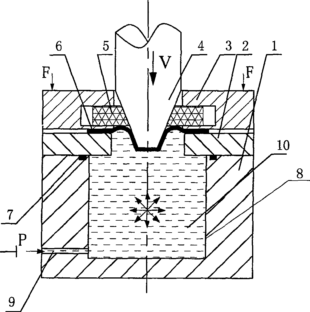
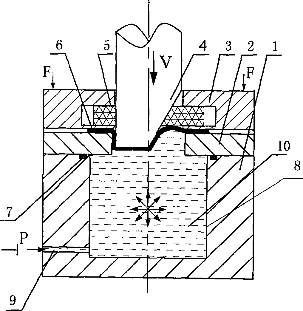
[0014] Specific implementation mode one: combine figure 1 The present embodiment will be described. This embodiment is composed of a fluid medium cavity 1, a die 2, a rigid blank holder 3, a punch 4 and a flexible support ring 5. The die 2 is arranged above the fluid medium cavity 1, and the lower plane of the die 2 is in contact with the The upper plane of the fluid medium cavity 1 is fixedly connected, the rigid blank holder 3 is arranged above the die 2, the inner ring of the rigid blank holder 3 has a groove, the flexible support ring 5 is arranged in the groove, and the flexible support ring 5 Urethane rubber material is used, and the plate blank 6 is placed between the rigid blank holder 3 and the die 2. There is a medium cavity 8 at the center of the upper surface of the fluid medium cavity 1, and the lower left side of the fluid medium cavity 1 is provided with A liquid injection hole 9 communicated with the medium chamber 8, and the liquid injection hole 9 communicat...

specific Embodiment approach 2

[0016] Specific implementation mode two: combination figure 1 The present embodiment will be described. Both the die 2 and the flexible support ring 5 in this embodiment are provided with inner holes for the punch 4 to pass through, and the maximum outer diameter of the punch 4 is smaller than the inner diameters of the rigid binder ring 3 and the die 2 . Ensure that the up and down movement of the punch 4 is deep drawn.

specific Embodiment approach 3

[0017] Specific implementation mode three: combination figure 1 The present embodiment will be described. The size difference between the inner diameter of the concave die 2 and the maximum outer diameter of the male die 4 in this embodiment is greater than the thickness of the formed plate blank 6 . When the plate blank 6 is pressed into the die 2, it will not break.


PUM


Abstract

The utility model relates to a device for preventing the breakage of the suspended area during the liquid-filled deep drawing of a conical part, which relates to a conical part forming device. It solves the disadvantage of deformation existing in the deep-drawing plate formed by the existing forming process, and also has the problem of relatively large impact in the process of applying pressure to the plate. The rigid binder ring (3) of the device of the present invention is arranged above the die (2), has a groove in the rigid binder ring (3), and the flexible support ring (5) is located in the groove, and the die (2) ) is arranged above the fluid medium cavity (1), and the liquid injection hole (9) is connected with the hydraulic system. The present invention also reduces the deep-drawing deformation of the plate, and can buffer the pressure during the process of applying pressure to the plate, reducing the impact on the plate. The large conical part avoids the rupture of the suspended area of ​​the conical part during liquid-filled deep drawing, which saves procedures, reduces costs and improves efficiency.

Description

technical field [0001] The invention relates to a device for rupturing a suspended area formed by liquid-filled deep drawing of a cone. Background technique [0002] In the sheet metal forming process, for the sheet metal parts whose shape and size are consistent with the punch and the height-to-diameter ratio is greater than 1, it is difficult to form in one time by ordinary drawing. At present, fluid is usually used as a force transmission medium to assist forming processing. The principle is to make the sheet close to the punch under the action of fluid back pressure, and the back pressure enhances the friction effect between the blank and the punch, forming a beneficial friction force, which can offset the punch. The partial tensile stress of the blank at the rounded corner improves the bearing capacity of the deformed blank, thereby avoiding the rupture of the material at the rounded corner of the punch and realizing the forming of the sheet metal part. The liquid-fill...

Claims


Application Information

Patent Timeline
Patent Type & Authority Patents(China)
IPC IPC(8): B21D26/02B21D37/10B21D26/021B21D26/031
Inventor 苑世剑徐永超
Owner HARBIN INST OF TECH
Why Eureka
Try Eureka