
Method for sending information and method and apparatus for receiving information

A technology for sending information and receiving end, which is applied in the fields of sending uplink power control information based on coherent detection and receiving uplink power control information based on coherent detection, which can solve the problems of reducing system capacity, occupying pilot information Pilot, wasting system sending resources, etc.

Active Publication Date: 2009-08-19
XFUSION DIGITAL TECH CO LTD
View PDF3 Cites 0 Cited by
  • Summary
  • Abstract
  • Description
  • Claims
  • Application Information

AI Technical Summary

Problems solved by technology

However, in the prior art, the pilot information Pilot occupies a large number of bits in the uplink power control information, so that the actual effective information TPC domain can only occupy a small number of bits
In this way, in order to meet the system-specific TPC error performance requirements, the sender needs to use higher transmit power to send uplink power control information, thereby increasing the self-interference of the system and reducing the capacity of the system
In addition, in the prior art, the period of power control is fixed as time slots, that is, the transmitting end continuously sends uplink power control information, while the receiving end does not need to continuously transmit uplink power control information in some specific application scenarios, such as slow moving application scenarios. The uplink power control information is received, therefore, the transmission resources of the system are wasted, and the performance of the system is reduced

Method used


Image

  • Method for sending information and method and apparatus for receiving information
  • Method for sending information and method and apparatus for receiving information
  • Method for sending information and method and apparatus for receiving information

Examples


Embodiment Construction

[0048] In order to make the purpose, technical solution and advantages of the present invention clearer, the present invention will be further described in detail below in conjunction with the accompanying drawings and specific embodiments.

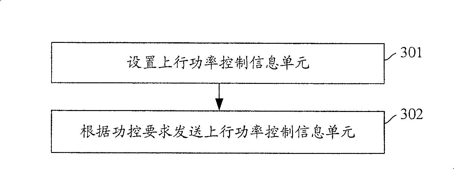
[0049] In order to reduce the power of sending uplink power control information, the present invention proposes a method for sending information, the core idea of ​​which is: set uplink power control information unit, the uplink power control information unit includes the pilot information Pilot of the first K time slots , and the control information including the TPC field of the last L time slots, where K and L are positive integers; the sending end sends the set uplink power control information unit to the receiving end.

[0050] Aiming at the method of sending information proposed by the present invention, the present invention also proposes a method of receiving information correspondingly, the core idea of ​​which is: the receiving e...


PUM


Abstract

The invention discloses a method for sending information and a method and device for receiving information. The device includes: a channel estimation unit, a channel deviation correction unit, a demodulation and information hard judgment unit, a channel acquisition unit and a time slot delay unit. The method for sending information is as follows: the uplink power control information unit is set to include the pilot information of the first K time slots and the control information of the last L time slots including the power control command word, K and L are positive integers; the sending end sends the uplink Power Control Information Element. The method of receiving information is as follows: the receiving end performs channel estimation based on the pilot information of the previous K time slots, performs channel correction, demodulation and hard judgment processing on the control information of the current time slot, and obtains the actual control information of the current time slot and channel information; after a time slot is delayed, channel estimation is performed according to the obtained channel information. The invention can reduce the power of sending the uplink power control information unit, thereby reducing the self-interference of the system and improving the capacity of the system.

Description

technical field [0001] The present invention relates to mobile communication technology, in particular to a method for sending uplink power control information based on coherent detection and a method and device for receiving uplink power control information based on coherent detection. Background technique [0002] In cellular systems, fast power control is an important factor to improve service quality of traffic. In order to realize fast power control, the uplink power control information sent by the cellular system includes: pilot information Pilot and control information including the power control command word TPC. The TPC in the control information is used to carry the power control command sent by the terminal to the base station, and the control information sometimes includes some control information other than the TPC, and the control information is an effective Information; pilot information Pilot is used for coherent detection power control command word TPC, and...

Claims


Application Information

Patent Timeline
Patent Type & Authority Patents(China)
IPC IPC(8): H04B7/005
Inventor 李化加
Owner XFUSION DIGITAL TECH CO LTD
Learn More