Antenna array, antenna transceiver system and radar system

A technology of transceiver system and antenna array, which is applied in the field of radar and can solve problems such as signal self-interference

Active Publication Date: 2019-09-13
TIME VARYING TRANSMISSION CO LTD
View PDF3 Cites 0 Cited by
  • Summary
  • Abstract
  • Description
  • Claims
  • Application Information

AI Technical Summary

Problems solved by technology

[0004] The embodiment of the present application provides an antenna array, an antenna transceiver system and a radar system, which solves the technical problem that the signal of the transmitting channel directly leaks to the receiving channel to form self-interference

Method used


Image

  • Antenna array, antenna transceiver system and radar system
  • Antenna array, antenna transceiver system and radar system
  • Antenna array, antenna transceiver system and radar system

Examples


Embodiment Construction

[0032] In order to enable those skilled in the art to better understand the solution of the present application, the technical solution in the embodiment of the application will be clearly and completely described below in conjunction with the accompanying drawings in the embodiment of the application. Obviously, the described embodiment is only It is a part of the embodiments of this application, not all of them. Based on the embodiments in this application, all other embodiments obtained by persons of ordinary skill in the art without making creative efforts belong to the scope of protection of this application.

[0033] This application designs an antenna array, an antenna system and a radar system, which solves the technical problem that the signal of the transmitting channel directly leaks to the receiving channel to form self-interference.

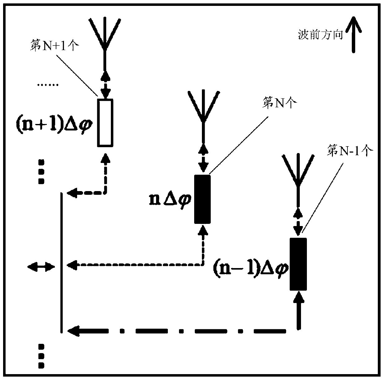
[0034] For ease of understanding, see figure 1 , figure 1 It is a schematic layout diagram of an antenna array provided by the em...


PUM


Abstract

The embodiment of the present application discloses an antenna array, including: N antenna units; the wavefront direction of the N antenna units is the same and the lateral spacing between any two is equal; the feeding phase of the N antenna units forms a first arithmetic sequence , the tolerance of the first arithmetic sequence is the preset phase difference; the distance from N antenna elements to the vertical plane in the wavefront direction forms the second arithmetic sequence, and the tolerance of the second arithmetic sequence is the preset distance difference; the preset distance The spatial phase difference between the N antenna elements formed by the difference with respect to the vertical plane cancels the preset phase difference; N is an integer greater than or equal to 2. When the antenna array is applied to the transmitting and receiving channels of the radar system, it can cancel the leakage signal, thereby greatly reducing self-interference, protecting the receiving channel of the radar system, and improving the sensitivity of the radar system. The embodiment of the present application also provides an antenna transceiving system and a radar system.

Description

technical field [0001] The present application relates to the technical field of radar, in particular to an antenna array, an antenna transceiving system and a radar system. Background technique [0002] With the continuous development of science and technology, there are more and more types of electronic products on the market. In addition to traditional personal computers and mobile terminals, emerging electronic products such as virtual reality devices have also appeared. For users, they often have multiple electronic devices, and often need to use multiple electronic devices at the same time. At this time, traditional human-computer interaction methods require users to use human-computer interaction devices installed on different electronic devices. It greatly affects the user experience and reduces work efficiency. Therefore, users urgently need a revolutionary human-computer interaction device, so that users can realize character input and various control functions wi...

Claims


Application Information

Patent Timeline
Patent Type & Authority Patents(China)
IPC IPC(8): H01Q1/50H01Q1/52H01Q21/00H01Q21/22G01S7/282G01S7/285G01S7/35
Inventor 徐强方有纲刘耀中刘耿烨李跃星
Owner TIME VARYING TRANSMISSION CO LTD
Why Eureka
Try Eureka