
Dual-purpose heat pump device for winter and summer

A technology of heat pump device and dual-use in winter and summer, applied in the field of dual-use heat pump device in winter and summer, can solve the problems of inability to recover low-temperature waste heat, performance degradation of the heat pump device, etc., and achieve the effects of reducing energy consumption, improving performance, and avoiding mutual offset.

Inactive Publication Date: 2009-08-19
XI'AN UNIVERSITY OF ARCHITECTURE AND TECHNOLOGY
View PDF10 Cites 1 Cited by
  • Summary
  • Abstract
  • Description
  • Claims
  • Application Information

AI Technical Summary

Problems solved by technology

The problem with this kind of heat pump device is: in the process of operation, the low-temperature waste heat discharged by the heat pump device cannot be recycled.
During normal operation in winter, it uses the outdoor side heat exchanger to absorb the heat of the outdoor air, and heats the indoor air through the indoor side heat exchanger to maintain the required room temperature. The heat exchanger absorbs heat from the indoor air to melt the frost between the fins of the outdoor heat exchanger. It can be seen that the conventional winter and summer dual-purpose heat pump device that uses outdoor air as a low-temperature heat source, during the winter defrosting operation , there is also mutual cancellation of cold and heat, resulting in a decline in the performance of the heat pump device

Method used


Image

  • Dual-purpose heat pump device for winter and summer
  • Dual-purpose heat pump device for winter and summer
  • Dual-purpose heat pump device for winter and summer

Examples


Embodiment 1

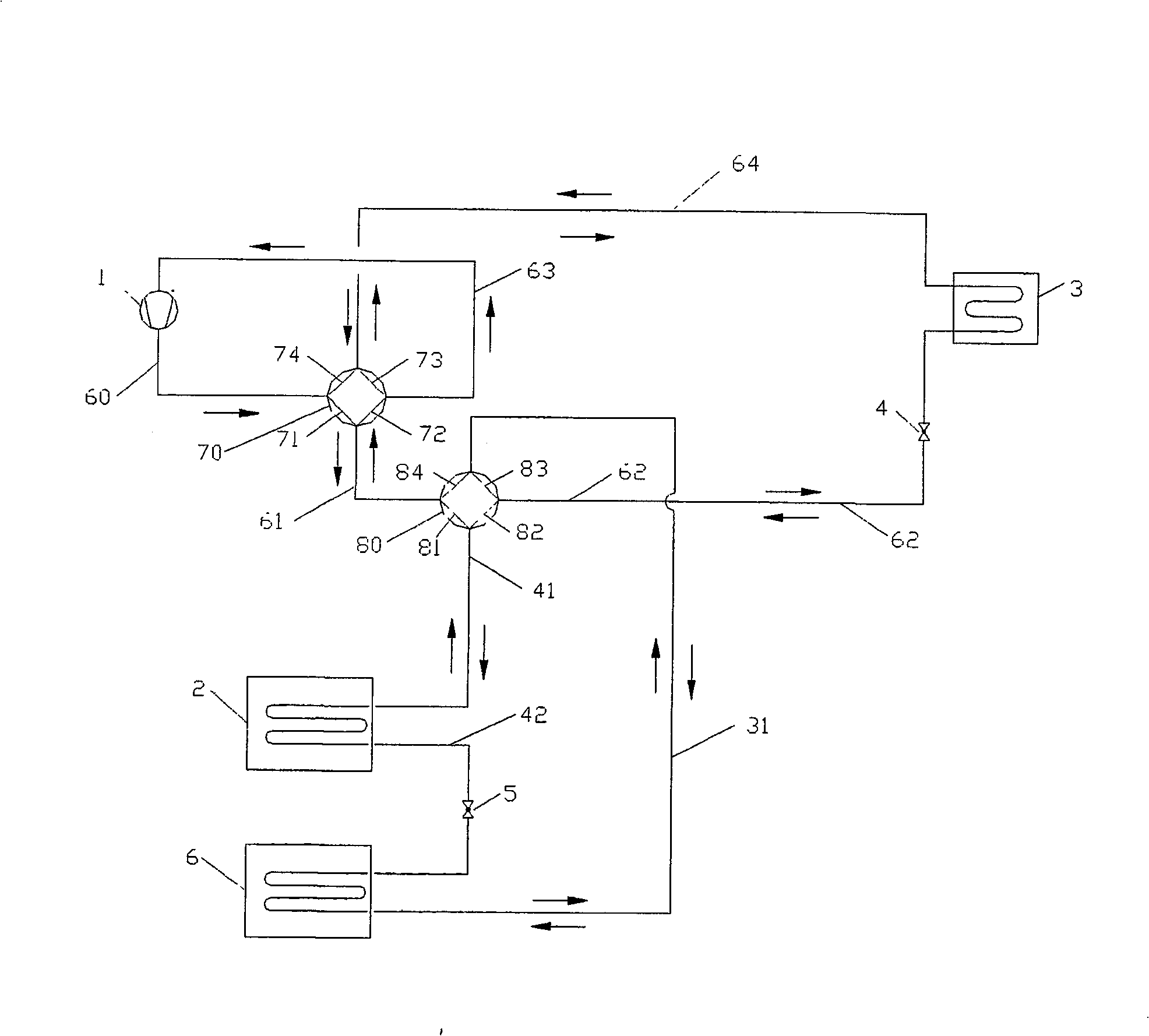
[0047] Such as figure 1 As shown, the whole device includes the following equipment: compressor 1, heat source side heat exchanger 2, user side heat exchanger 3, first throttling mechanism 4 and second throttling mechanism 5, second heat exchanger 6, four-way Valves 70 and 80.

[0048] Four passages 71, 72, 73, 74 are provided inside the first four-way valve 70, and four passages 81, 82, 83, 84 are also provided inside the second four-way valve 80; there are four passages outside each four-way valve. Connection points, each connection point is connected to two internal channels.

[0049] The user-side heat exchanger 3 is a refrigerant-air heat exchanger.

[0050] The heat source side heat exchanger 2 and the second heat exchanger 6 are also refrigerant-air heat exchangers, they can be installed separately; they can also be installed in the same shell, and the air is provided by at least one air-driven device for transporting air A device can be a blower or a fan.

[0051] ...

Embodiment 2

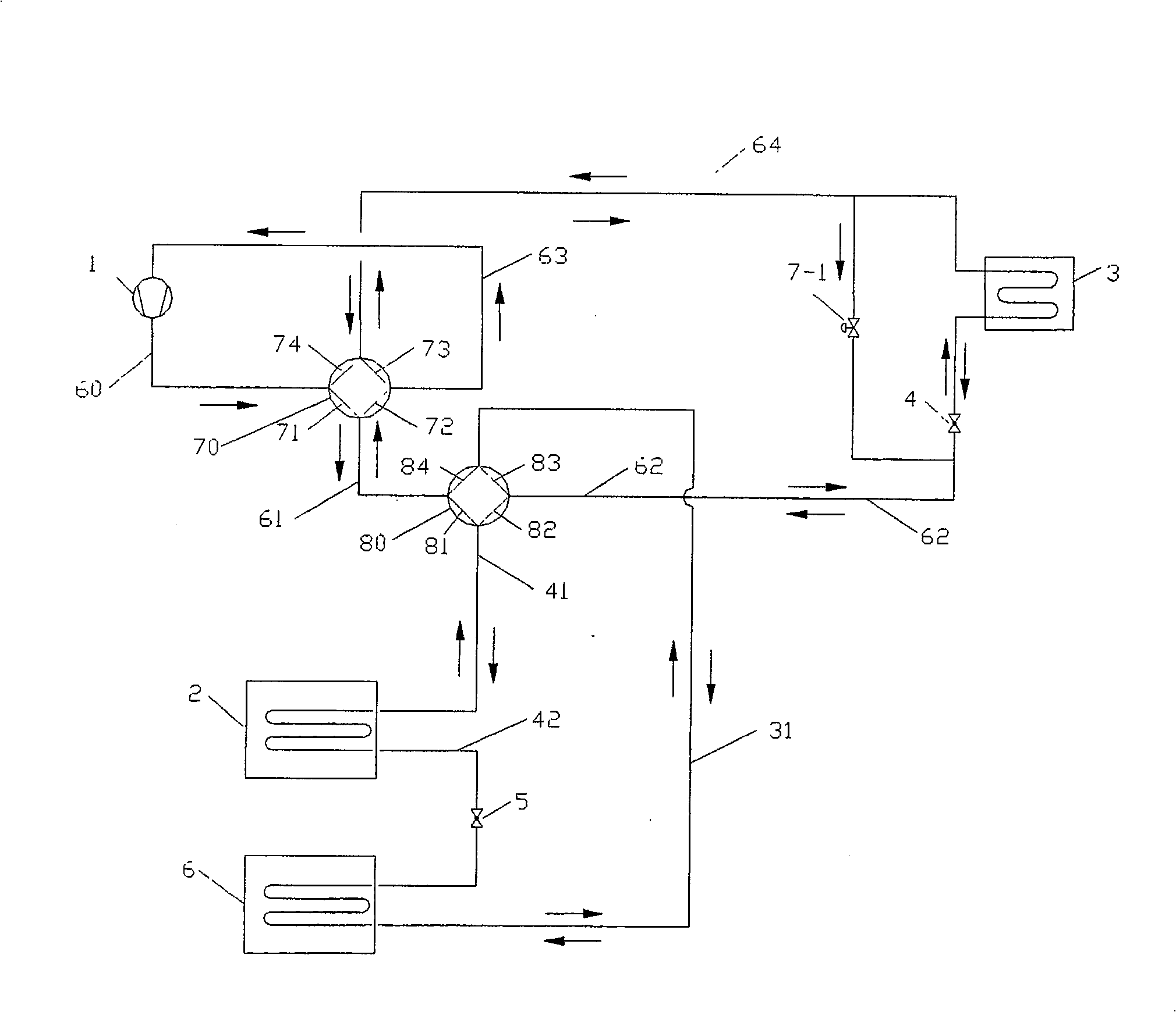
[0067] figure 2 As shown, the heat exchanger 3 on the user side, the heat exchanger 2 on the heat source side, and the second heat exchanger 6 are all refrigerant-air heat exchangers. Compared with Embodiment 1, the only difference is that the first flow direction control valve 7-1 is added, which is connected in parallel with the user-side heat exchanger 3 and the first throttling mechanism 4, while other equipment and connections in the device The way is exactly the same as in Example 1.

[0068] During the working process of the cooling cycle in summer and the heating cycle in winter in embodiment 2, the first flow direction control valve 7-1 is closed, so the working process of the cooling and heating cycle in embodiment 2 is exactly the same as that in embodiment 1.

[0069] During the working process of the winter defrosting cycle in Embodiment 2, the first flow direction control valve 7-1 is opened, and the first throttling mechanism 4 is closed. Pass through the use...

Embodiment 3

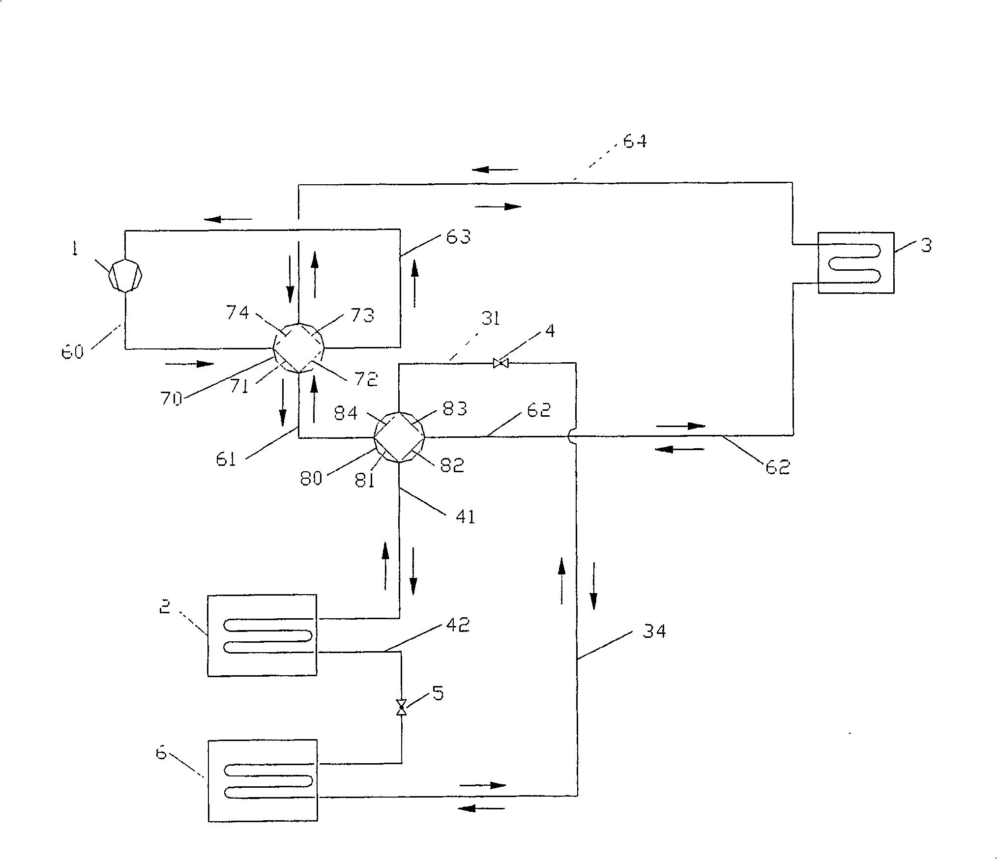
[0072] image 3 As shown, the heat exchanger 3 on the user side, the heat exchanger 2 on the heat source side, and the second heat exchanger 6 are all refrigerant-air heat exchangers. The difference between it and Embodiment 1 is: in Embodiment 1, the first throttling mechanism 4 is set on the pipe connecting the second four-way valve 80 and the user-side heat exchanger 3; but in Embodiment 3, the first A throttling mechanism 4 is arranged on the pipeline connecting the second four-way valve 80 and the second heat exchanger 6 .

[0073] Apart from that, in Embodiment 3, other devices are connected in the same way as in Embodiment 1. When working, the circulation loops of the summer refrigeration cycle, the winter heating cycle and the winter defrosting cycle and the functions of each device are also the same as those in Embodiment 1.

[0074] In the process of implementation, there is also the following scheme: one end of the first throttling mechanism 4 is connected to the ...


PUM


Abstract

The invention discloses a heat pump device which can be used both in summer and winter. The heat pump device comprises a compressor, a heat source side heat exchanger, a user side heat interchanger, a throttling mechanism and a four-way valve; and the heat pump device also comprises a second heat interchanger, a second throttling mechanism and a second four-way valve. The four-way valve is provided with four nodes, a four-way valve node is connected with the output end of the compressor through a pipeline, the four-way valve node is connected with the input end of the compressor through the pipeline, the four-way valve node is connected with one end of the user side heat interchanger through the pipeline, the four-way valve node is connected to the node of the four-way valve through the pipeline, the other node of the four-way valve is connected with the other ends of the user side heat interchanger in sequence through the pipeline and the throttling mechanism, the four-way valve node is connected with one end of the heat source side heat exchanger, and the other end of the heat source side heat exchanger is connected with the four-way valve node through the throttling mechanism and the second heat interchanger. The heat pump device produces the hot water to refrigerate or heat in the operation process. The recycling produces the low temperature afterheat. In the process of refrigeration cycle in summer and heating cycle in winter, the super cooling of a refrigeration agent can be realized. The invention is suitable for the industrial and civil use.

Description

technical field [0001] The invention relates to a refrigeration and heating device, and is particularly suitable for a dual-purpose heat pump device for winter and summer. Background technique [0002] At present, the conventional winter and summer dual-purpose heat pump device is composed of a compressor, a user-side heat exchanger, a heat source-side heat exchanger, a throttling mechanism, and a four-way valve. It relies on the four-way valve to switch between winter and summer operating conditions; In the process, the user-side heat exchanger absorbs heat from the user to provide cooling for the user, and the absorbed heat is discharged into the low-temperature heat source through the heat source side heat exchanger; during winter operation, the heat source side heat exchanger absorbs heat from the low-temperature heat source The heat is then supplied to the user through the user-side heat exchanger; now commonly used low-temperature heat sources include air, soil, and wa...

Claims


Application Information

Patent Timeline
Patent Type & Authority Patents(China)
IPC IPC(8): F25B13/00F25B30/02F25B41/04F25B47/02
CPCF25B2313/02742
Inventor 刘雄
Owner XI'AN UNIVERSITY OF ARCHITECTURE AND TECHNOLOGY
Learn More