Laterally sliding tensioner

A tensioning device and traverse technology, which is applied in the conveyor control device, transportation and packaging, conveyor objects, etc., can solve the problems that the height and space of the workshop are difficult to meet the requirements, the height requirements of the workshop are relatively high, and the assembly requirements are high. To achieve the effect of saving height and space, flexible tensioning activities and stable performance

Inactive Publication Date: 2009-08-19
MIRACLE AUTOMATION ENG CO LTD
View PDF5 Cites 0 Cited by
  • Summary
  • Abstract
  • Description
  • Claims
  • Application Information

AI Technical Summary

Problems solved by technology

The disadvantage of this tensioning method is that the manufacturing cost is high and the use has certain limitations; the requirements for the height of the factory building are relatively high, especially in the case of a large tensioning stroke, it is difficult to meet the requirements for the height of the factory building; The heavy gravity pulls the sprocket down. In order to ensure the flexibility of the tensioning sprocket when it falls, the requirements for assembly are relatively high.

Method used


Image

  • Laterally sliding tensioner
  • Laterally sliding tensioner

Examples


Embodiment Construction

[0010] Below the present invention will be further described in conjunction with the embodiment in the accompanying drawing:

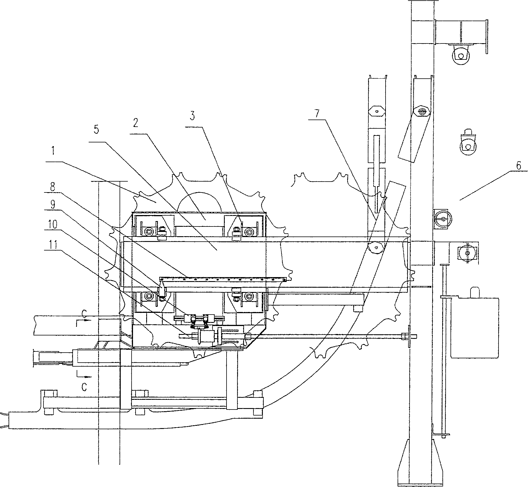
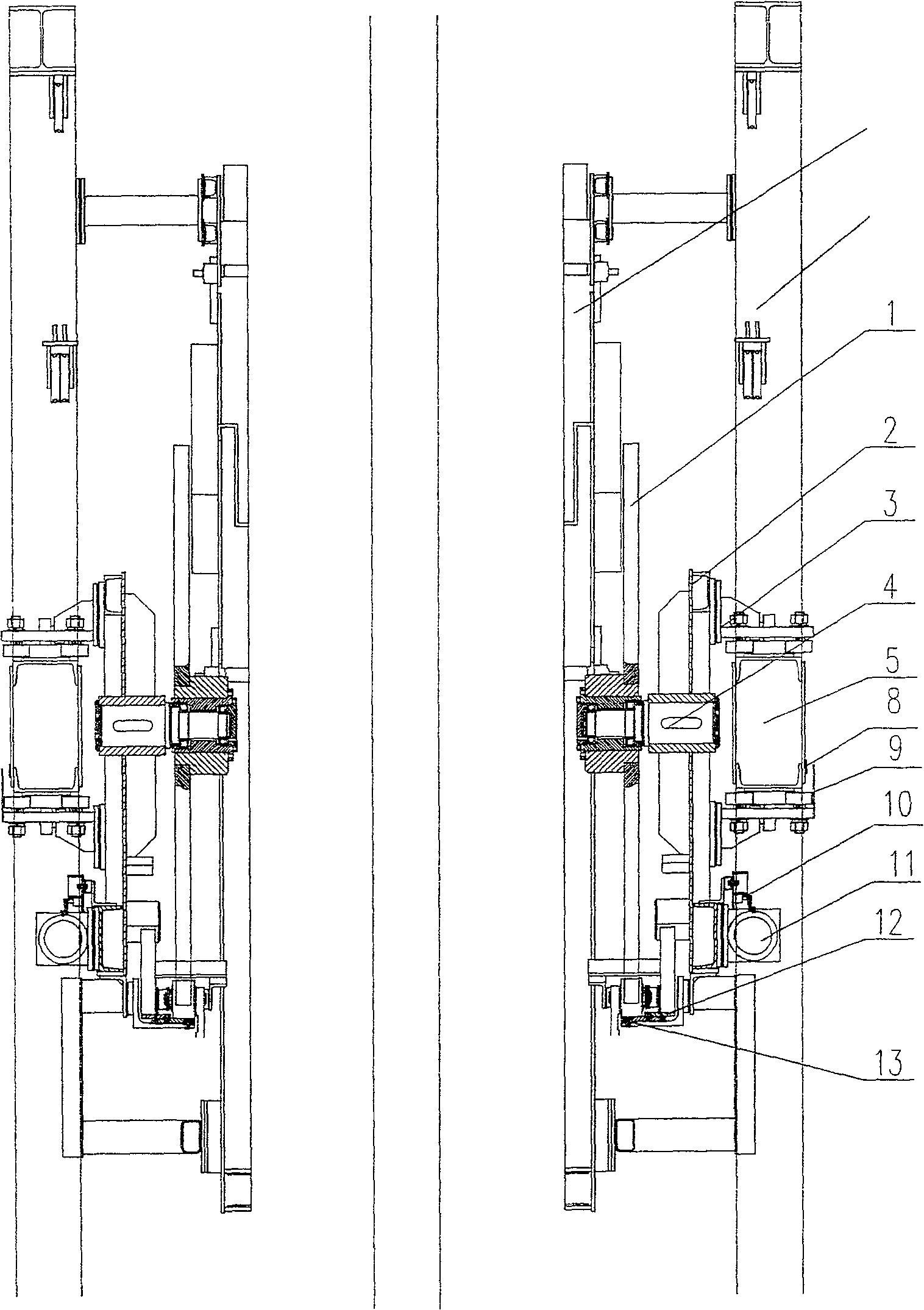
[0011] The present invention mainly consists of a tensioning sprocket 1, a tensioning movable frame 2, a guide wheel assembly 3, a shaft 4, a guide rail 5, a labor-saving counterweight device 6, a floating flip frame guide rail 7, a tensioning stroke indicating ruler 8, a tensioning Tight travel pointer 9, travel switch assembly 10, long-distance adjustable signaling device 11, chain fixed track 12, chain movable track 13 and other components.

[0012] As shown in the figure: the guide rail 5 is connected with the frame, the guide wheel assembly 3 is installed on the tensioning movable frame 2, and the tensioning movable frame 2 is movably mounted on the guide rail 5, and one end of the shaft 4 is connected to the tensioning movable frame The frame 2 is connected, the other end is connected with the tensioning sprocket 1 by a bearing, and the labor-sav...


PUM


Abstract

A traverse type tensioning device relates to the technical field of conveying machinery, in particular to a tensioning device of a chain transmission mechanism. According to the design scheme provided by the present invention, the guide rail is connected with the frame, the guide wheel assembly is installed on the tension movable frame, and the tension movable frame is movably mounted on the guide rail, and one end of the shaft is connected with the tension movable frame , the other end is connected with the tensioning sprocket by bearing, and the labor-saving counterweight device is connected with the guide wheel assembly. The invention can meet the requirements of small space, large tensioning stroke and high precision of the rotary immersion conveyor system, thereby providing a method of using steel wire ropes to realize steering through pulley blocks, so that the longitudinal movement of the counterweight can be converted into a tensioning frame and a tensioning chain. The wheel moves laterally along the guide rail, and uses the characteristics of the movable pulley to reduce the weight and volume of the counterweight part of the new tensioning mechanism.

Description

technical field [0001] The invention relates to the technical field of conveying machinery, in particular to a tensioning device of a chain transmission mechanism. Background technique [0002] In the prior art, most of the gravity tensioning mechanisms move longitudinally, that is, the tensioning is realized by moving the tension frame and the sprocket along with the counterweight in the direction of gravity. The disadvantage of this tensioning method is that the manufacturing cost is high and the use has certain limitations; the requirements for the height of the factory building are relatively high, especially in the case of a large tensioning stroke, it is difficult to meet the requirements for the height of the factory building; Heavy gravity pulls the sprocket down. In order to ensure the flexibility of the tensioning sprocket when it falls, the requirements for assembly are relatively high. Contents of the invention [0003] The purpose of the present invention is ...

Claims


Application Information

Patent Timeline
Patent Type & Authority Patents(China)
IPC IPC(8): B65G23/44B65G21/20B65G43/00B65G49/02
Inventor 杨雷杨敏杨勇
Owner MIRACLE AUTOMATION ENG CO LTD
Why Eureka
Try Eureka