
Air passage and its control method

A control method and air duct technology, applied in the direction of electrical program control, electric temperature control, power supply test, etc., can solve the problems of high price, inconvenient movement, consuming test resources, etc., and achieve low manufacturing cost and mobile equipment Convenient, accurate test results

Inactive Publication Date: 2009-07-29
EMERSON NETWORK POWER CO LTD
View PDF5 Cites 0 Cited by
  • Summary
  • Abstract
  • Description
  • Claims
  • Application Information

AI Technical Summary

Problems solved by technology

[0003] The existing method has several disadvantages: ① Temporary air ducts are made during the test, which has great randomness
The size and shape of the air ducts made by each person are different, the fans used are different, and the positions of the modules installed in the air ducts are also different, resulting in different standard scales of the test, poor consistency and repeatability of the test
②The wind speed at different positions in the air duct is quite different, that is, the uniformity of the wind is poor
The reason is that the wind generated by the fan rotation has a certain spiral, without any wind uniform treatment, the quality of the wind is difficult to meet the requirements of the test
③Axial fans are generally used for fans, and the motor of the fan is also in the air duct. After the temperature rises or changes, the speed of the motor will be affected, and the wind speed will also change accordingly. That has changed, and the equipment to measure wind speed at high temperatures is quite expensive
④ When making module derating curves, at high temperatures (such as temperatures above 120°C), the axial motor may be damaged or thermally protected, making the test impossible; ⑤ Axial fans often work in high temperature or high and low temperature environments, It will seriously affect its service life. In some cases, it may be damaged after one or two tests, which will bring inconvenience to the test and increase the cost of the test.
⑥ The thermostat needs to be occupied during the test, which consumes test resources and is inconvenient to move

Method used


Image

  • Air passage and its control method
  • Air passage and its control method
  • Air passage and its control method

Examples


Embodiment Construction

[0022] The present invention will be further elaborated below according to the drawings and specific embodiments.

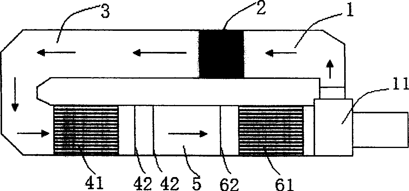
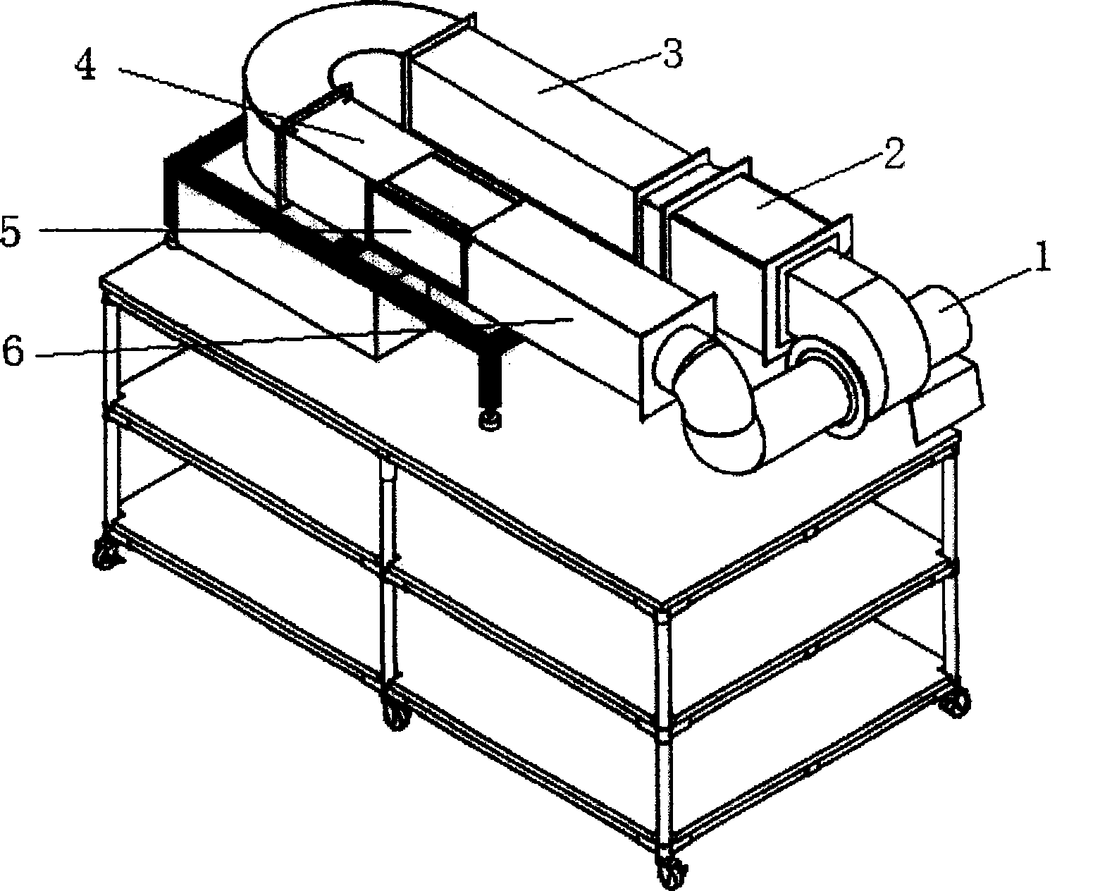
[0023] Such as figure 1 , figure 2 As shown, an air duct of the present invention is a closed-loop air duct, and the air duct part is mainly divided into a pressurization section 1, a heating section 2, a return air section 3, a flow equalization section 4 and a test section 5, and its control Part includes frequency converter (not marked in the figure) and controller (not marked in the figure).

[0024] Wherein, the pressurization section 1 adopts a centrifugal fan 11, the input end of the blade of the centrifugal fan 11 is connected with the output end of the test section 5, and the output end of the fan 11 outputs a high-pressure airflow with a certain wind speed to the heating section 2. The motor of the centrifugal fan 11 is arranged outside the air duct and connected with the frequency converter. Therefore, the speed of the fan 11 can be controlled by ...


PUM


Abstract

The present invention relates to air passage and its control method, and is especially heating air passage for testing air cooled apparatus and its control method. The air passage includes one pressurizing section, one test section, and one heating section set between the pressurizing section and the test section, and has heater set in the heating section for heating the airflow the pressurizing section outputs. The present invention has the advantages of low resource consumption, open-looped control of wind speed and the closed-loop control operate temperature resulting in low cost, convenient wind speed and temperature regulation, accurate measurement result, etc.

Description

technical field [0001] The invention relates to an air duct and a control method thereof, in particular to a heating air duct and a control method thereof which are mainly used in heat generation tests and reliability tests of devices for cooling by external air supply. Background technique [0002] At present, the newly developed products of the communication secondary power supply are basically open or board-mounted power supplies with substrates. The board-mounted power supplies are dissipated by system air cooling. The following performance indicators and derating curves require more precise control of the wind speed and temperature of the board-mounted power module test environment. The method adopted at present is to make a simple air duct with cardboard or plexiglass, add a DC fan at the mouth of the air duct, and then put the air duct in a thermostat for testing. [0003] The existing methods have several disadvantages: ① Temporary air ducts are made during the test...

Claims


Application Information

Patent Timeline
Patent Type & Authority Patents(China)
IPC IPC(8): G01R31/40G05B19/02G05D23/19
Inventor 宋学东
Owner EMERSON NETWORK POWER CO LTD
Learn More