High-frequency power amplifying circuit

A power amplifying circuit and amplifying circuit technology, which are applied to power amplifiers, DC amplifiers with modulator-demodulators, etc., can solve the problem of long rise time, large fall time of the output radio frequency signal, and the delay of the marker machine cutting off the laser. Long and other problems, to achieve the effect of eliminating the match head phenomenon, increasing the descending speed, and increasing the descending time

Inactive Publication Date: 2009-07-22
HUAZHONG UNIV OF SCI & TECH
View PDF3 Cites 0 Cited by
  • Summary
  • Abstract
  • Description
  • Claims
  • Application Information

AI Technical Summary

Problems solved by technology

The performance index given by the Q switch driver of NEOS company is that the rise time is less than 500ns, and the fall time is less than 100ns; The index of falling time is much better than that of rising time. If the rising time is too long, it means that the time delay for the marking machine to turn off the laser is too long, which will affect the marking quality.
[0005] There is a high-frequency power amplifier circuit inside the existing acousto-optic Q-switch driver. The disadvantage of this circuit is that the rise time of the output radio frequency signal is too long, which is much longer than the fall time, which affects the performance of the system.

Method used


Image

  • High-frequency power amplifying circuit
  • High-frequency power amplifying circuit
  • High-frequency power amplifying circuit

Examples


Embodiment Construction

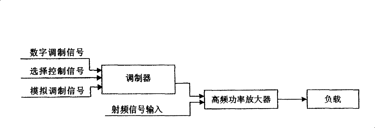
[0019] The invention includes a modulator and a high frequency power amplifier.

[0020] Depend on figure 1 As shown, the modulator receives an externally input digital modulation signal or analog modulation signal, and amplifies the input digital modulation signal or analog modulation signal to a modulation signal with strong drive capability to provide the required signal for the high-frequency power amplifier, high-frequency power The amplifier amplifies the incoming RF signal to the level required by the load.

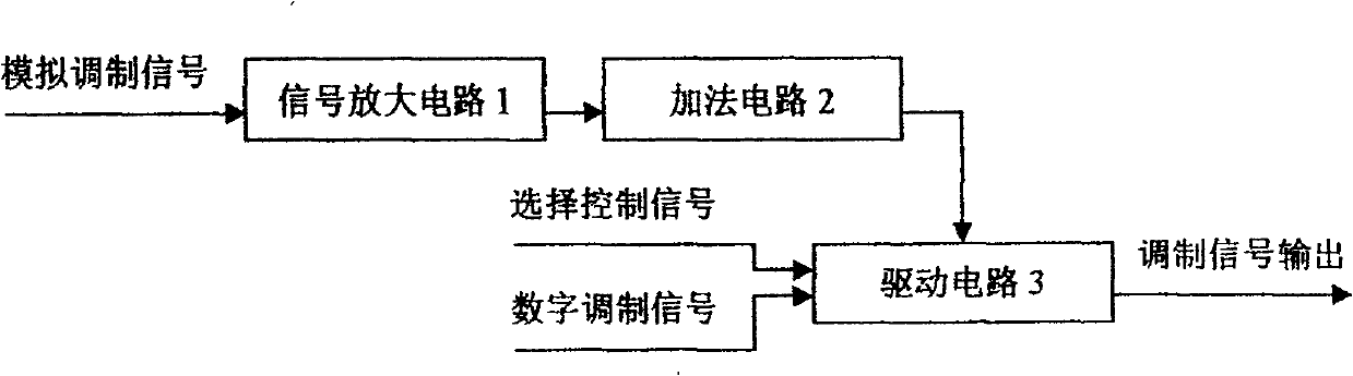
[0021] Depend on figure 2 As shown, the modulator is composed of a signal amplification circuit 1, an addition circuit 2 and a drive circuit 3. The signal amplifying circuit 1 and the adding circuit 2 adopt general signal amplifying circuits and adding circuits; the driving circuit 3 adopts a specially designed driving circuit.

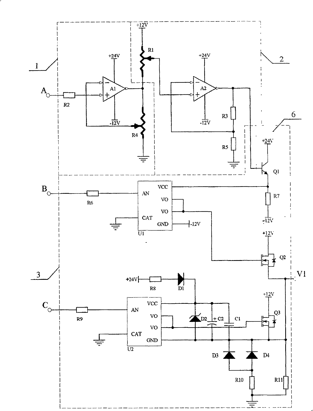
[0022] Depend on image 3 As shown, a connection method of the signal amplifying circuit 1 can be: resistor R 2 One end A is connec...


PUM


Abstract

The invention discloses a high-frequency power amplifier circuit. The high-frequency power amplifier is composed of a modulator and a power amplifier. The modulator includes a signal amplifier circuit, an addition circuit and a drive circuit. The power amplifier includes a first-stage amplifier circuit and a second-stage amplifier circuit. Amplifying circuit, the present invention specially designs the driving circuit and the second-stage amplifying circuit. The second-stage amplifying circuit contains a high-frequency choke coil, and the high-frequency choke coil adopts a magnetic material made of manganese-zinc or nickel-zinc. ring. The power amplifying circuit can not only realize high-efficiency high-frequency power amplification, but also greatly increase the rising and falling speeds of the envelope of the final output radio frequency signal. The invention can be applied to the acousto-optic Q switch driver of Nd:YAG laser marking machine and the communication system adopting amplitude modulation.

Description

technical field [0001] The invention belongs to the technical field of power amplification, and is especially used for a high-frequency power amplification system requiring high-speed switching. Background technique [0002] Generally, the efficiency of a high-frequency power amplifier increases as the output power of the amplifier increases in a linear range, reaching a maximum efficiency at a certain point in the amplifier's saturated operation. [0003] In the FM communication system, due to the constant envelope nature of the signal, the amplifier can always be in a saturated state, so that higher efficiency can be achieved, but in the communication system that requires linear amplification, the signal envelope is no longer constant, so the amplifier efficiency is reduced. [0004] In the field of laser marking, at present, the well-known manufacturers of acousto-optic Q-switch drivers for Nd:YAG laser marking machines include NEOS in the United States and Guilin Xingch...

Claims


Application Information

Patent Timeline
Patent Type & Authority Patents(China)
IPC IPC(8): H03F3/20H03F3/38
Inventor 刘玉吴旦昱张瑛黄勇肖振宇钟国辉
Owner HUAZHONG UNIV OF SCI & TECH
Why Eureka
Try Eureka