Rotary kiln hook nail arrangement method

A rotary kiln and hook nail technology, applied in the field of rotary kiln, can solve the problems of loose lining castable structure, affecting the lining of the rotary kiln, affecting the use of the rotary kiln, etc., so as to reduce pollution, improve the ability to resist mechanical vibration, and save maintenance. effect of cost

Active Publication Date: 2009-07-15
GUIZHOU BRANCH CHINA ALUMINUM IND
View PDF8 Cites 0 Cited by
  • Summary
  • Abstract
  • Description
  • Claims
  • Application Information

AI Technical Summary

Problems solved by technology

[0002] Used in pouring of rotary kiln lining for carbon calcination of petroleum coke in aluminum electrolysis industry, Φ14 stainless steel hook nails are arranged within 3 and a half meters behind the sixth tuyere, and Φ10 stainless steel hook nails are arranged in other parts; stainless steel hook nails and pouring The expansion of the material uses the cloth tape wrapped around the hook nails to form an expansion joint. After the cloth tape is wrapped, due to the construction one by one, it is easy for the construction personnel to tear off the cloth tape when entering and leaving the kiln. There is no expansion joint between the stainless steel hook nail and the castable. When the stainless steel hook nails expand during operation, the expansion force destroys the structure of the lining castable, resulting in a loose structure of the lining castable, which affects the life of the kiln
The root size of the original stainless steel hook nails is 25mm. The stainless steel hook nails are fixed by welding the roots of the stainless steel hook nails on the rotary kiln barrel. During use, the Φ14 stainless steel hook nails and the Φ10 stainless steel hook nails are separated from each other due to mechanical vibration. The parts directly welded on the rotary kiln barrel fall off as a whole, which affects the falling off of the rotary kiln lining and affects the use of the rotary kiln

Method used


Image

  • Rotary kiln hook nail arrangement method
  • Rotary kiln hook nail arrangement method
  • Rotary kiln hook nail arrangement method

Examples


Embodiment 1

[0024] The root of the original stainless steel hook nail 2 is set to 40mm, which increases the welding strength of the root, and the welding length is 40mm. The maximum tensile force borne by the stainless steel hook nail 2 with a fully welded length of 40 mm is 1.6 times that of the stainless steel hook nail with a fully welded length of 25 mm.

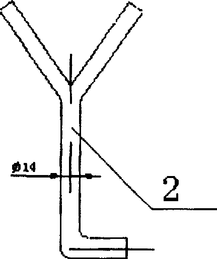
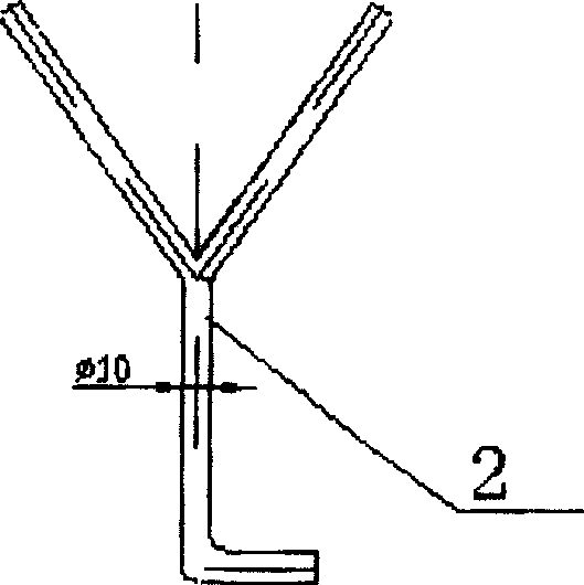
[0025] Arrange Φ14 stainless steel hook nails 2 between the secondary air nozzle and the tertiary air nozzle of the rotary kiln cylinder 4 within 10.5 meters, and the longitudinal distance between the hook nails is set to 200mm; the other parts of the rotary kiln cylinder 4 are arranged Φ10 Stainless steel hook 2.

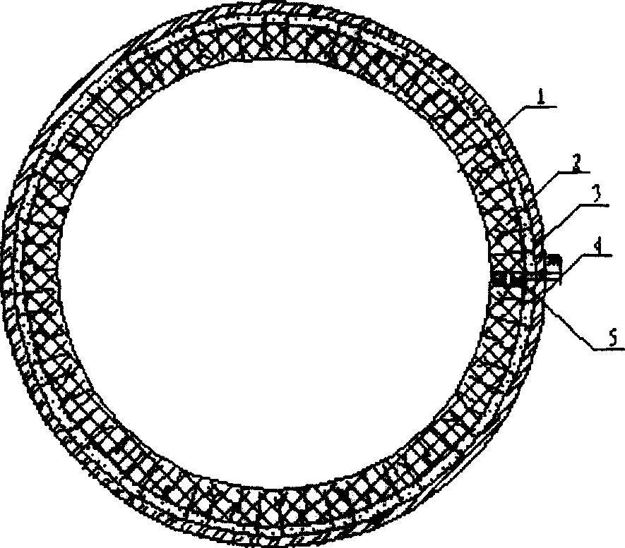
[0026] Use black tape to wrap the stainless steel hook nail 2, which not only ensures the design thickness, but also meets the expansion requirements; weld the stainless steel hook nail 2 on the rotary kiln shell 4 according to the direction of the root; then pour light castable material 3; make the formwork ; Pouring a...


PUM


Abstract

The invention relates to a rotary kiln, in particular to a method for arranging stainless steel hooks and nails in the pouring of the inner lining of the rotary kiln used for carbon calcining petroleum coke in the aluminum electrolysis industry. The hook nail arrangement method of the rotary kiln of the present invention includes the following steps: 1) setting the hook nail structure; 2) wrapping the cloth belt; 3) arranging the stainless steel hook nails of Φ14 to be arranged at 10.5 meters between the secondary tuyere and the tertiary tuyere Within, the longitudinal distance between the hook nails on the rotary kiln shell is 200mm; 4) Weld the stainless steel hook nails on the rotary kiln shell according to the roots facing the rotary kiln shell. The invention has the following beneficial effects: the method for arranging the hooks and nails of the rotary kiln effectively prolongs the service life of the rotary kiln, saves a lot of maintenance costs, and reduces environmental pollution caused by industrial garbage such as overhauled kiln linings. The invention is suitable for the maintenance of the rotary kiln used for carbon calcining petroleum coke in the aluminum electrolysis industry and the construction of a new kiln.

Description

technical field [0001] The invention relates to a rotary kiln, in particular to a method for arranging stainless steel hooks and nails in the pouring of the inner lining of the rotary kiln used for carbon calcining petroleum coke in the aluminum electrolysis industry. Background technique [0002] Used in pouring of rotary kiln lining for carbon calcination of petroleum coke in aluminum electrolysis industry, Φ14 stainless steel hook nails are arranged within 3 and a half meters behind the sixth tuyere, and Φ10 stainless steel hook nails are arranged in other parts; stainless steel hook nails and pouring The expansion of the material uses the cloth tape wrapped around the hook nails to form an expansion joint. After the cloth tape is wrapped, due to the construction one by one, it is easy for the construction personnel to tear off the cloth tape when entering and leaving the kiln. There is no expansion joint between the stainless steel hook nail and the castable. When the st...

Claims


Application Information

Patent Timeline
Patent Type & Authority Patents(China)
IPC IPC(8): F27D1/16
Inventor 王平王广稳付明录朱革新张爱新董卫平李育祥刘兴安
Owner GUIZHOU BRANCH CHINA ALUMINUM IND
Why Eureka
Try Eureka