Piston machine

A piston and mechanical technology, applied in the field of mechanical construction, can solve the problems of increasing the minimum volume, reducing the production rate of piston mechanical volume filling, reducing the flow cross section of suction valve and pump suction valve, etc., to achieve the effect of reducing volume

Inactive Publication Date: 2009-05-20
MICHAELLA K CORP
View PDF7 Cites 0 Cited by
  • Summary
  • Abstract
  • Description
  • Claims
  • Application Information

AI Technical Summary

Problems solved by technology

[0005] A disadvantage of the known piston machine during its use as a compressor is the occurrence of a significant waste of space, as well as during the suction and pumping of the working body due to the positioning on one cover of the cylinder of the suction and pumping valve The hydraulic loss increases the minimum volume between the cover and the piston due to the volume of the valve and reduces the flow cross-section of both the suction valve and the pumping valve which together occupy the same surface of the cover, which reduces the piston mechanical Volumetric productivity and filling of cylinders with working bodies
Also, sufficient cooling of the piston is not provided in this piston machine

Method used


Image

  • Piston machine
  • Piston machine

Examples


Embodiment Construction

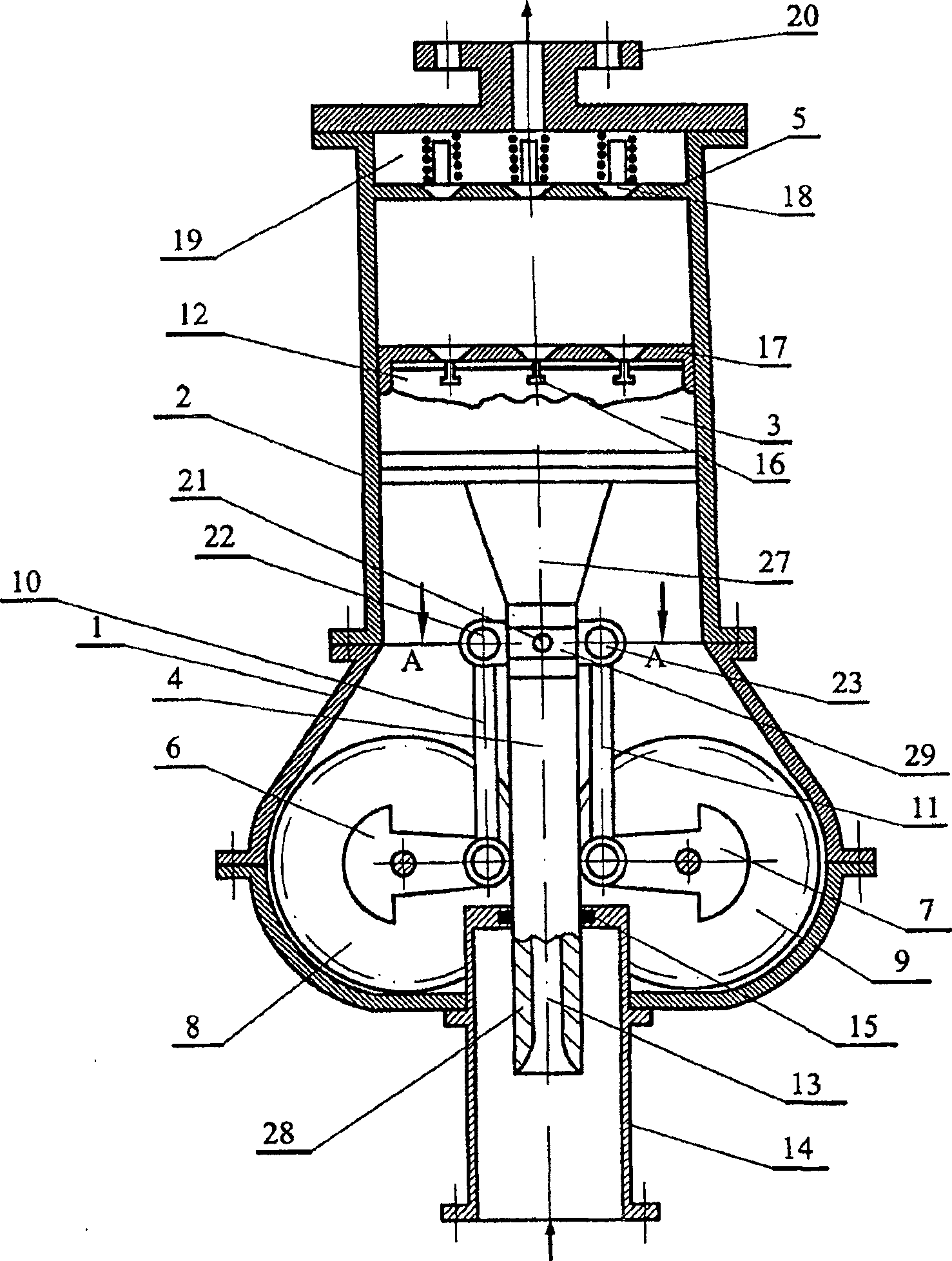
[0015] A piston machine formed as a piston compressor has a crankcase 1 on which a cylinder 2 is fastened, a cover 5 arranged on the cylinder, two parallel crankshafts 6 and 7, wherein a piston 3 with a piston rod 4 is arranged in the cylinder 2 , two parallel crankshafts 6 and 7 with balancing weights arranged symmetrically with respect to the axis of the cylinder 2 and connected to each other, with the possibility of rotation in opposite directions via connected spur gears 8 and 9 .

[0016] Crossbeam 29 is connected with piston rod 4, two connecting rods 10 and 11, each connecting rod 10 and 11 is hingedly connected on one end to corresponding crankshaft 6 or 7, and the other end is hingedly connected to At the respective ends of the beam 29, the above-mentioned two ears 25 and 26 have fingers 22 and 23 fastened to them. The piston rod 4 has a partial square cross-section in the region of the connection with the connecting rod. The piston rod 4 of the piston 3 is hingedly ...


PUM


Abstract

A machine recommended for use in the energy generation industry as an engine, pump and compressor. The machine has a crankcase 1 , a cylinder 2 with a piston 3 and a piston rod 4 , two crankshafts 6 and 7 rotating in opposite directions. The internal cavity 12 of the piston communicates with the through axial passage 13 of the piston rod 4, which is arranged in the crankcase and has the possibility of reciprocating movement in the suction pipe 14; A diffuser 27 is formed on the side of the cavity 12 and a stirrer 28 is formed from the side of the suction tube 14 . The pumping valve 18 is arranged on the head 5 of the cylinder, the suction valve 16 is arranged on the front wall of the piston; wherein the piston rod 16 and the connecting rods 10 and 11 of the crankshafts 6 and 7 are hingedly connected with the beam 29 . The present invention provides a reduction in wasted space and a reduction in hydraulic losses.

Description

technical field [0001] The invention relates to the field of mechanical construction and can be used in compressors, pumps and internal combustion engines. Background technique [0002] Piston machines are known which have a crankcase on which a cylinder is fastened and a cover arranged on the cylinder, wherein a piston with a piston rod is arranged in the cylinder. A connecting rod system with a crosshead is connected to the crankshaft and has a guide in the lower part of the crankcase (certificate no. 905499 of the inventor's USSR, FO1 B9 / 00 1978). [0003] A disadvantage of the known piston machine is that it does not solve the problem of reducing wasted space, reducing hydraulic losses in the valves and insufficient cooling of the machine's piston, which reduces its volumetric productivity. [0004] Piston machines are known which have a crankcase on which the cylinders are fixed and covers arranged on the cylinders, suction and pumping valves, two parallel crankshafts,...

Claims


Application Information

Patent Timeline
Patent Type & Authority Patents(China)
IPC IPC(8): F01B9/02F02B75/32F01L3/20F01L21/04F01L25/04F02B75/06F02D9/04F02D29/04F02F3/00F04B39/00
CPCF01L25/04F02D9/04F04B39/0022F04B39/0016F02F3/00F01L21/04F02D29/04F02B75/065F01L3/205F04B39/0094F01B9/02F02B75/32
Inventor R·N·沃罗别夫A·M·泽林斯基
Owner MICHAELLA K CORP
Why Eureka
Try Eureka