
Sealing property testing equipment

A testing device and technology for sealing performance, which are used in fluid tightness testing, measuring devices, and liquid tightness measurement using liquid/vacuum degree. Safety and other issues, to achieve the effect of strong safety

Inactive Publication Date: 2009-04-29
SUZHOU BMC SEALING TECH CO LTD
View PDF3 Cites 0 Cited by
  • Summary
  • Abstract
  • Description
  • Claims
  • Application Information

AI Technical Summary

Problems solved by technology

[0003] Due to the reciprocating movement of the valve stem in the high-pressure chamber, the actual volume of the high-pressure chamber changes, which seriously affects the accuracy of the detection data, and the leakage is often small, which is prone to reading errors, making the accuracy of the packing sealing performance test results At the same time, one end of the valve stem directly extends into the high-pressure chamber. At the end of the valve stem, the gas in the high-pressure chamber will generate a large thrust on this end of the valve stem, which will affect the bearing of the valve stem connecting parts. High pressure requirements make the test device extremely unsafe, and the valve stem may be ejected at any time, which may even lead to accidents

Method used


Image

  • Sealing property testing equipment
  • Sealing property testing equipment

Examples


Embodiment Construction

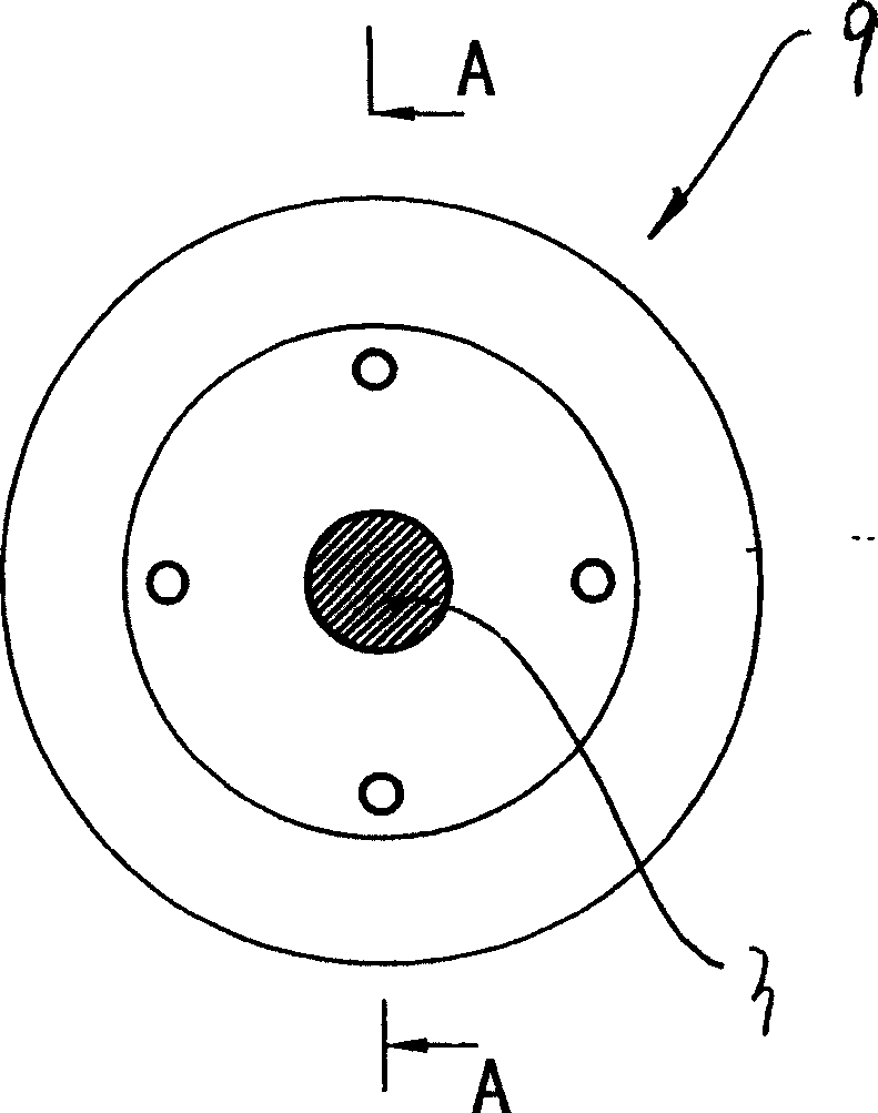
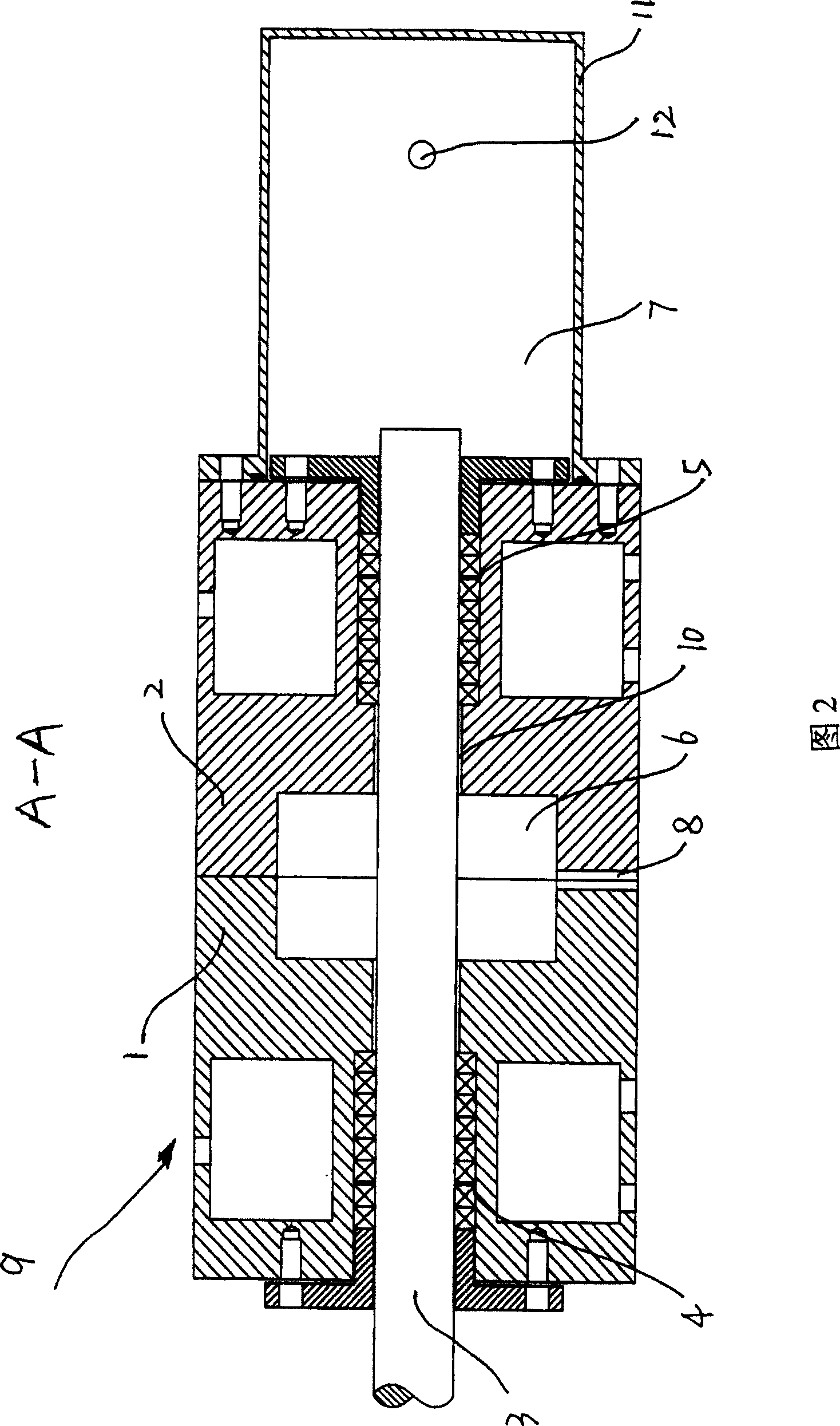
[0016] See attached figure 1 Referring to accompanying drawing 2, a sealing performance testing device includes a main body 9 and a valve stem 3. The main body 9 has a valve stem chamber 10 penetrating through the main body 9. The valve stem 3 is slidably arranged in the valve stem chamber 10. Part of the valve stem The cavity 10 is radially enlarged to form a packing cavity for placing the packing, and the main body 9 has a high-pressure cavity 6 communicating with the stem cavity 10 . The main body 9 is composed of a first main body 1 and a second main body 2 , the first main body 1 is in contact with the second main body 2 , and the stem chamber 10 runs through the first main body 1 and the second main body 2 . The high pressure chamber 6 is symmetrically located on the abutting surface of the first body 1 and the second body 2 .

[0017] The second main body 2 has a first through hole 8 , the first through hole 8 communicates with the high pressure chamber 6 and the outer...


PUM


Abstract

The device comprises: a body with a through valve cavity with part radial enlarged as filler cavity for to-and-fro or spiral motion of a valve rod, a high-pressure cavity connected to former cavity and a first through hole both on the body, a sealing cover on one body end with a second through hole and a testing cavity. This invention has high precision, and well security.

Description

technical field [0001] The invention relates to a sealing performance testing device for testing packing sealing performance and service life. Background technique [0002] In the prior art, a sealing performance testing device includes a main body and a valve stem. The main body has a valve stem cavity penetrating through the main body. The valve stem is slidably arranged in the valve stem cavity, and part of the valve stem cavity radially changes A packing chamber is formed, the outer surface of the main body is connected with a high-pressure chamber, and one end of the valve stem extends into the high-pressure chamber. There is a through hole in the high-pressure chamber, and the tester measures the gas change in the high-pressure chamber through the through hole. When performing the packing test, the packing is injected into the stuffing box, and high-pressure gas or liquid is introduced into the high-pressure chamber, so that the packing can seal the high-pressure mediu...

Claims


Application Information

Patent Timeline
Patent Type & Authority Patents(China)
IPC IPC(8): G01M3/26G01M3/00
Inventor 马志刚安源胜
Owner SUZHOU BMC SEALING TECH CO LTD
Learn More