Foundation for an offshore wind energy plant

A technology for wind power generation equipment and seabed, which is applied to wind turbine components, wind energy power generation, wind turbines, etc., can solve the problems of poor material utilization and high cost

Inactive Publication Date: 2009-04-01
AERODYN ENG GMBH
View PDF4 Cites 5 Cited by
  • Summary
  • Abstract
  • Description
  • Claims
  • Application Information

AI Technical Summary

Problems solved by technology

This results in poor material utilization and therefore in heavy, costly components

Method used


Image

  • Foundation for an offshore wind energy plant
  • Foundation for an offshore wind energy plant
  • Foundation for an offshore wind energy plant

Examples


Embodiment Construction

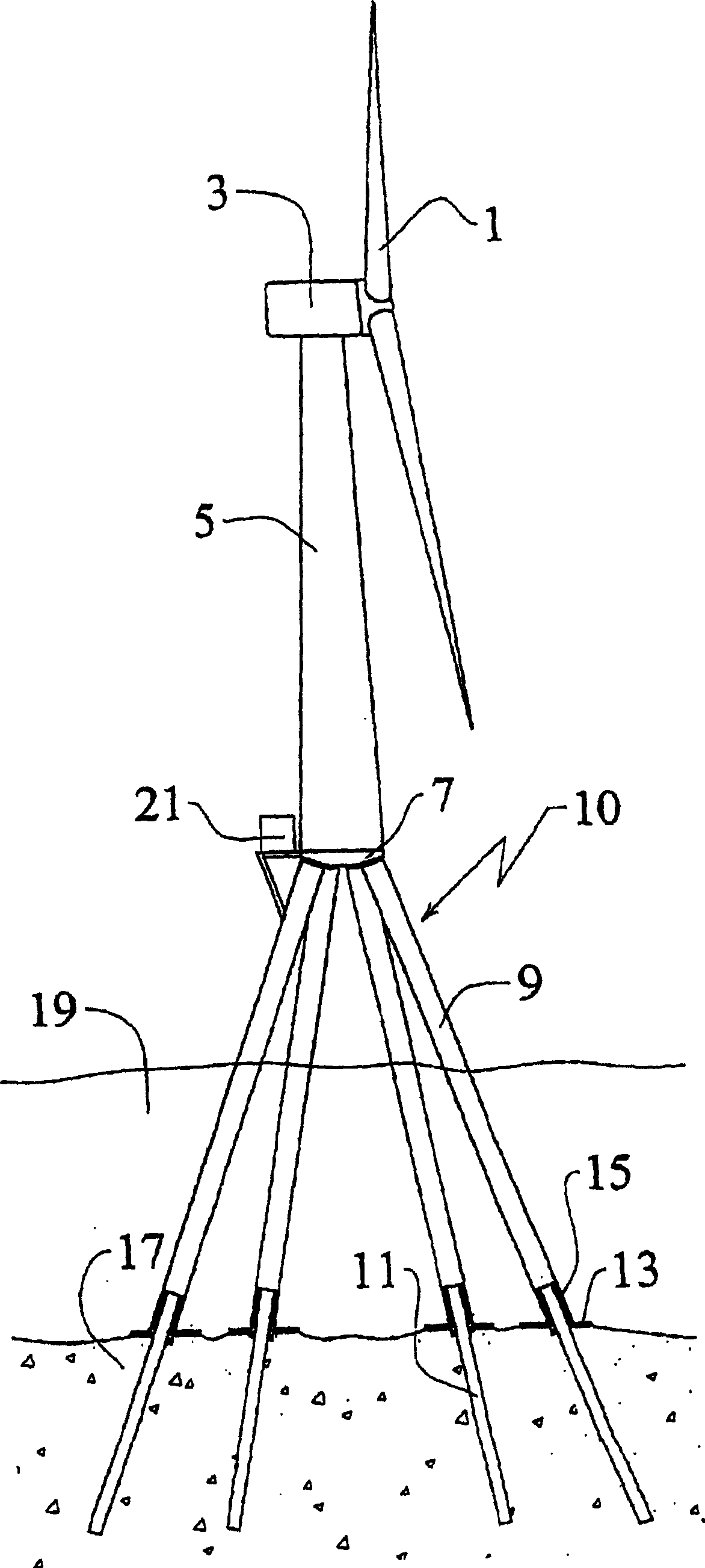
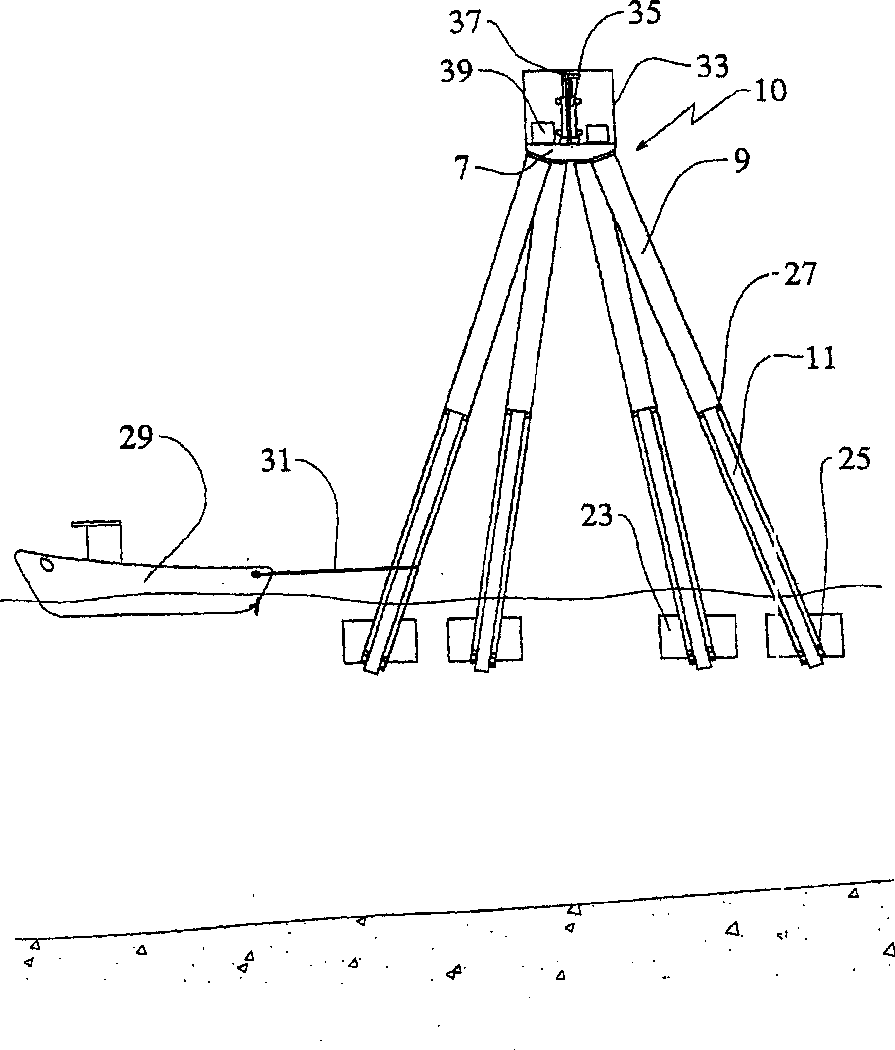
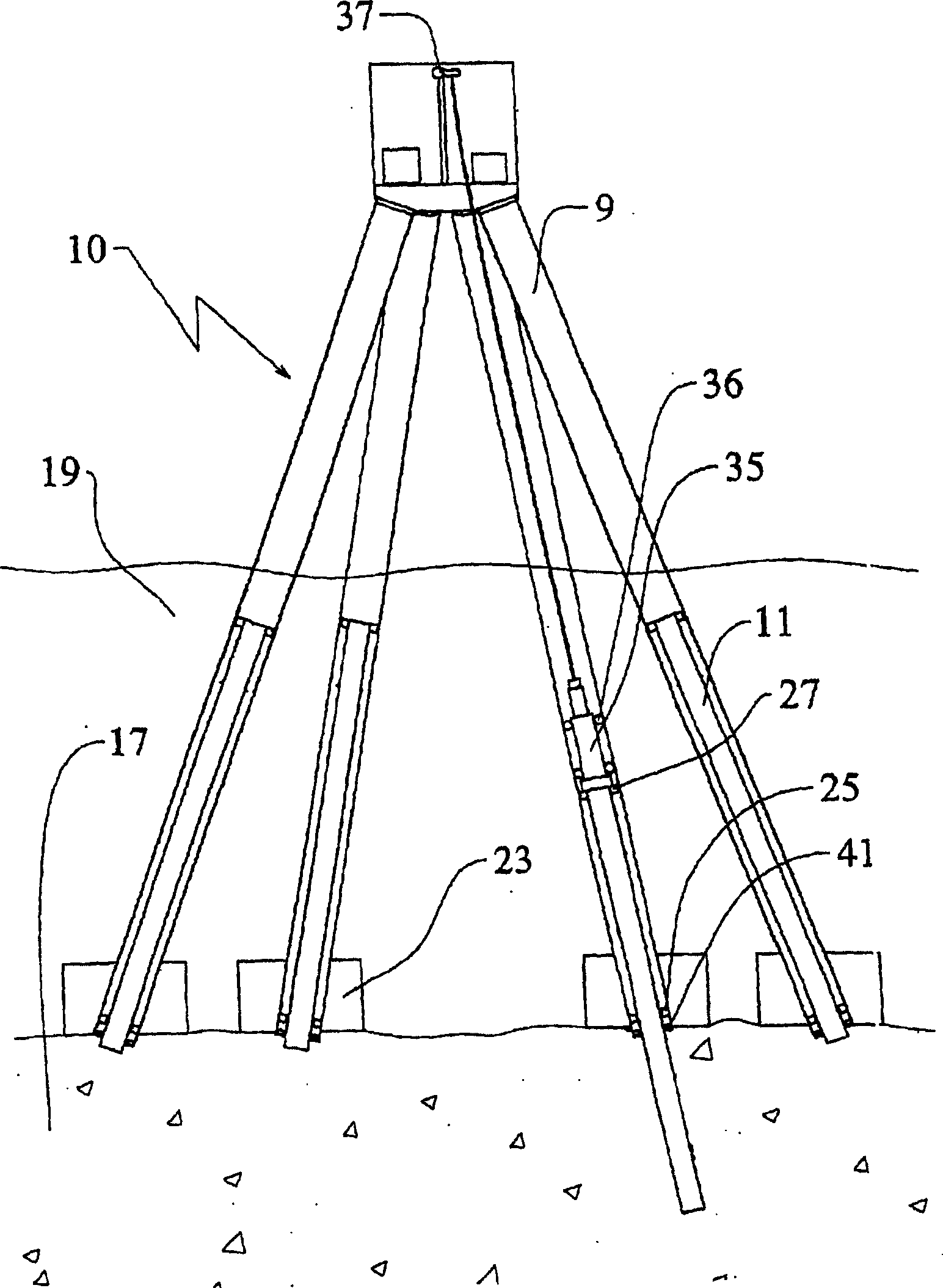
[0040] figure 1 The overall installed offshore wind power plant shown includes a rotor 1 in the form of converting wind energy into usable energy. The equipment pod 3 houses the necessary parts and components and is connected to the tower 5 by a swivel connection. Tower 5 has a flange at its lower end. The tower 5 is connected to the load distribution 7 by suitable connections. A plurality of base legs 9 are attached to the load distribution member 7 at a small angle of 10° to 30° relative to the vertical. A plurality of foundation legs 9 are connected by driven piles 11 driven into the seabed 17 . Base plates 13 are installed at the lower ends of the base legs to reduce the sinking of the structure into the seabed 17 . A potting or connection with a suitable material such as concrete is provided between the foundation leg 9 and the driven pile 11 . The overall height of the foundation 10 with its foundation legs 9 is dimensioned such that the largest expected waves will ...


PUM


Abstract

The invention relates to foundation for an offshore wind energy plant (WEA), comprising a load distribution element (7) supporting the tower (5) of the WEA provided with a gondola (3) and a rotor (1) and a plurality of foundation legs (9) which support the load distribution element (7) and which extend in an inclined manner towards the outside in relation to the vertical. The central axes (M) of the foundation legs (9) intersect with the circular surface (K) which is circumscribed by the external diameter of the tower (5) in the joining plane (V) of the load distribution element (7) and said tower (5).

Description

technical field [0001] The invention relates to a foundation and a plurality of outwardly directed foundation legs for an offshore wind power plant (WPP) with a load distribution element supporting a WWP tower with a nacelle and a rotor, a plurality of The base legs are inclined relative to the vertical and support the load distribution member. Background technique [0002] Offshore wind power equipment has developed rapidly since the 21st century. The equipment was redesigned for specific offshore situations and partly completely new solutions were developed for local problems. One of the main problems in the development of offshore wind power is the high cost, mainly for the base of the equipment and the connection structure to the ground. [0003] There are many different base designs. In shallow water up to a depth of about 5 to 7 meters it is advantageous to use a caisson base made of concrete. A prefabricated floatable or buoyant cavity concrete element on dry rock...

Claims


Application Information

Patent Timeline
Patent Type & Authority Patents(China)
IPC IPC(8): F03D1/00E02B17/00E02B17/02E02D27/42
CPCE02B2017/0091E02D27/42F03D11/045E02B17/0034E02B2017/0078E02B17/0004E02B17/02Y02E10/727F05B2240/95F05B2260/301F03D13/22E02D27/425Y02E10/72
Inventor S·西格弗里德森
Owner AERODYN ENG GMBH
Why Eureka
Try Eureka