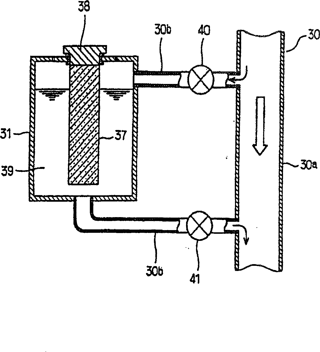
Washing machine sterilizing reagent kit and its sterilizing method

A technology for a kit and a washing machine, which is applied to other washing machines, control devices of washing machines, washing devices, etc., can solve the problem that the volume of the sterilizing water generating mechanism 22 is not improved, and achieve a simple structure, a large space, and a long service life. Effect

Active Publication Date: 2009-03-25
HAIER GRP CORP +1
View PDF5 Cites 0 Cited by
  • Summary
  • Abstract
  • Description
  • Claims
  • Application Information

AI Technical Summary

Problems solved by technology

[0009] like image 3 As shown, the sterilizing water generating mechanism 22 mainly includes a water storage tank 23, a water supply chamber 24, an accommodation chamber 25, an accommodation container 29 for accommodating solids, a fixed filter 30, solids 28, a water injection port 21, a siphon 26, an overflow pipe 27, etc. , the general design idea of ​​this invention is the same as that of reference document 1 and reference document 2. In the sterilizing water generating mechanism 22, the water supply chamber 24 and the accommodation chamber 25 are arranged side by side, and the water flows into the accommodation chamber 25 through the water supply chamber 24. The siphon tube 26 1. The bottom of the overflow pipe 27 is integrally formed in the water supply chamber 24, so the volume of the entire sterilizing water generating mechanism 22 has not been improved.

Method used


Image

  • Washing machine sterilizing reagent kit and its sterilizing method
  • Washing machine sterilizing reagent kit and its sterilizing method
  • Washing machine sterilizing reagent kit and its sterilizing method

Examples


Embodiment 1

[0035] As shown in Figure 5, it is a cross-sectional view of an embodiment of the disinfection kit of the present invention. In the water inlet hole 2, it includes: a box body 1, a water injection hole 2 arranged at the bottom of the box body 1, and a drainage hole 3. The water injection hole 2 Connected with the water inlet valve 21, the box body 1 includes: an outer box 11 and an inner box 12, the outer box 11 and the inner box 12 are fixedly arranged as one, and the siphon device 4 is arranged on the inner box 12 At the bottom, a baffle 5 is provided between the outer box 11 and the inner box 12 on the side where the drainage hole 3 is provided, and an overflow hole 51 is opened on the upper part of the baffle 5 to maintain the water level in the outer box 11 at the equilibrium water level H The bottom of the baffle plate 5 is provided with a drain hole 52 that facilitates part of the water flowing into the washing tub, and the top of the inner box 12 is provided with a cove...

Embodiment 2

[0041] Figure 5 is a cross-sectional view of another embodiment of the disinfection kit of the present invention, its structure is substantially the same as that shown in Figure 4, the difference is that no independent water inlet valve is provided at the water inlet 2 The inner box 12 can also be fixedly sleeved in the outer box 11 from top to bottom, and a drainage control valve 31 is provided on the drainage path of the drainage hole 3 .

[0042] The disinfection method in this embodiment is the same as the main steps disclosed in the embodiment, the difference is that the water intake is controlled by the softener control valve, and the water discharge is controlled by the drain control valve 31 .

[0043] In step a, the water source first enters the outer box 11 through the water injection hole 2, a part of the water flows into the washing tub through the drain hole 52 and the drain hole 3, and the other part of the water passes through the siphon device 4 arranged at the ...


PUM


Abstract

The washer disinfectant reagent box comprises one outer box and one inside box. The outer box has water inlet hole and water draining hole in the bottom, and baffle set on the water draining hole side with water overflow hole in the upper part and water draining hole in the bottom. The inside box has one siphon unit in the bottom for water inlet passage and water outlet passage, and the siphon unit makes the reagent block not being soaked completely for long service life. The disinfectant reagent box of the present invention has novel and simple structure, is integrated and convenient in mounting, and occupies less space inside the washer.

Description

technical field [0001] The invention relates to a disinfection method, in particular to a washing machine disinfection method, and at the same time relates to a disinfection kit designed for realizing the method. Background technique [0002] The disinfection method and device structure thereof of existing disinfection washing machine, open literature is as follows: [0003] Reference document 1, the application number is: 00128762.1 Chinese patent literature discloses a washing machine and its washing method, for the inner tub (washing bucket), there is a setting part for setting solids, and the solids are slowly released by contacting with water. Chlorine acid, and water containing hypochlorous acid released from the solid is supplied into the inner tub, thereby utilizing the bactericidal action of hypochlorous acid to suppress the growth of bacteria in the inner tub and laundry. The invention can inhibit mildew, odor, yellowing, infection and the like. There is a laundr...

Claims


Application Information

Patent Timeline
Patent Type & Authority Patents(China)
IPC IPC(8): D06F39/02D06F33/02A61L2/16
Inventor 曹春华吕佩师许升王升明田云
Owner HAIER GRP CORP
Why Eureka
Try Eureka