
Composite lens system

A compound lens system and lens technology, applied in the field of compound lens systems, can solve the problems of unavoidable spherical aberration, increased lens weight, small lens size, etc., and achieve good optical imaging performance and avoid spherical aberration effects.

Active Publication Date: 2009-03-11
RUGAO LANTU KNITTING CLOTHING CO LTD
View PDF8 Cites 0 Cited by
  • Summary
  • Abstract
  • Description
  • Claims
  • Application Information

AI Technical Summary

Problems solved by technology

After adopting the above structure, the lens size is small, and the lenses are all made of spherical glass lenses. Although the processing is easy, but the material is too much to use glass materials to make glass lenses, which increases the weight of the lens, and inevitably brings spherical aberration, which affects imaging. performance

Method used

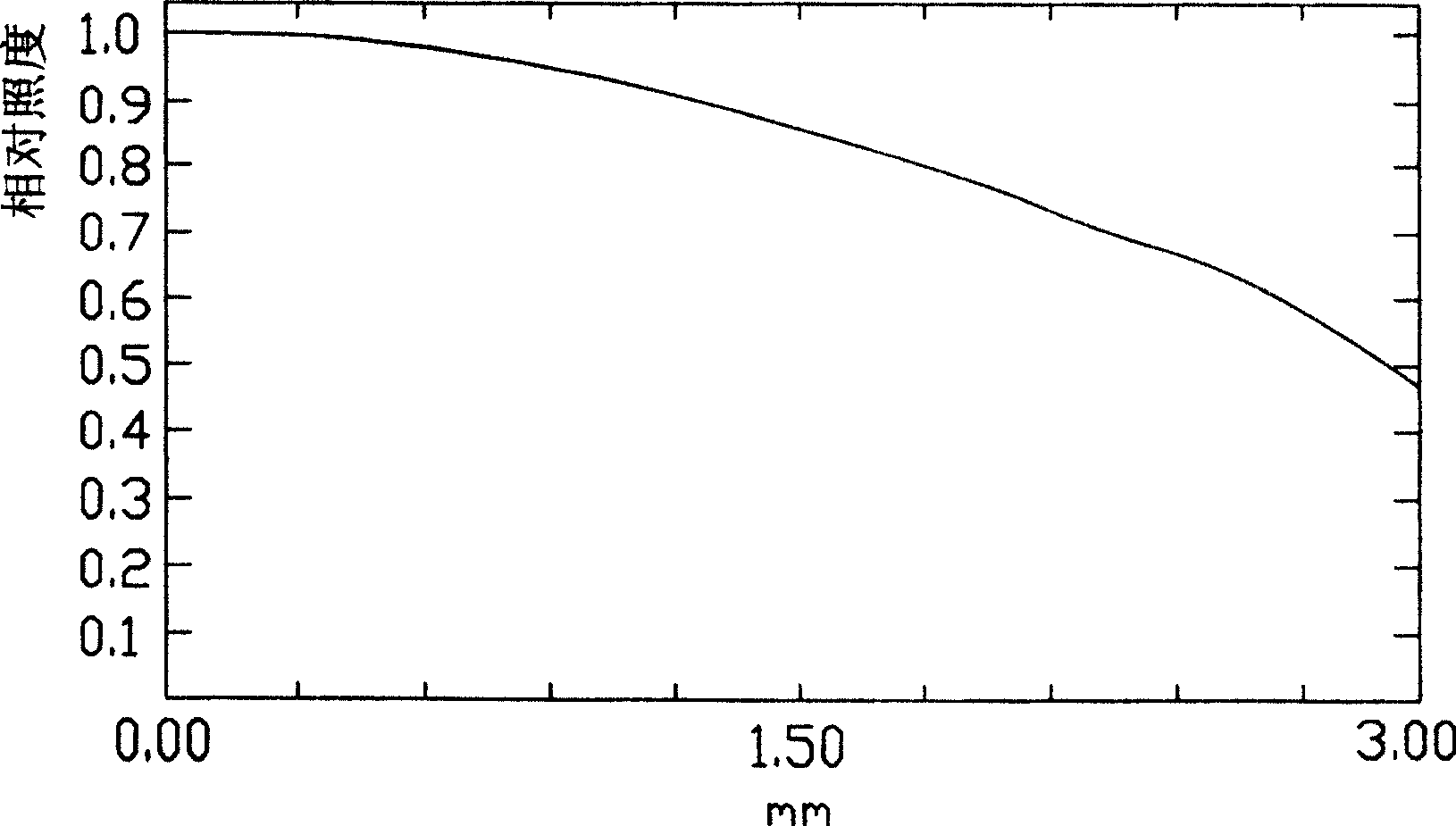
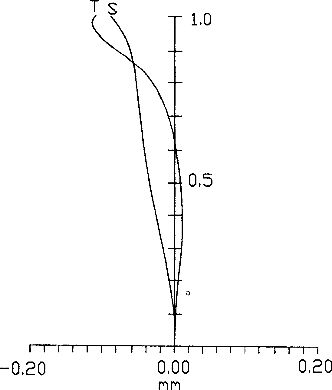

Image

  • Composite lens system
  • Composite lens system
  • Composite lens system

Examples


Embodiment Construction

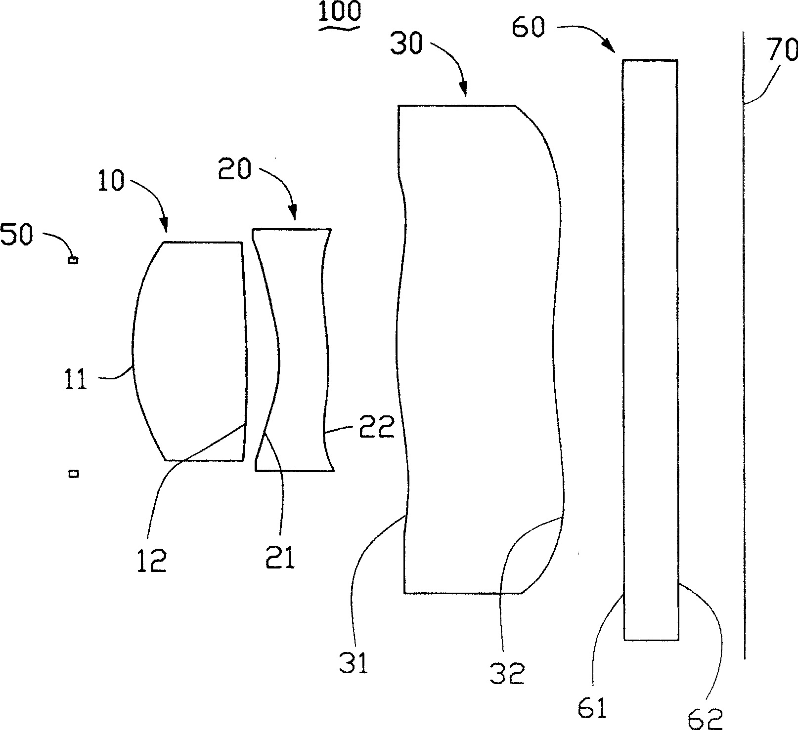
[0034] see figure 1 , which is a compound lens system 100 according to the first embodiment of the present invention, including: a first lens 10, a second lens 20, and a third lens 30 arranged in order from the object side to the image side. In addition, a diaphragm 50 is disposed on the object side of the first lens 10 , and a flat plate element 60 and an image sensor 70 are sequentially disposed on the image side of the third lens 30 .

[0035] The first lens 10 is a lens with a positive focal length, and the range of refractive index and dispersion is 1.551 1 2 2 3 3 <60 is made of optical plastic material, the fifth surface 31 is convex, and the sixth surface 32 is concave. In this embodiment, the preferred plastic material model for making the third lens is E48R.

[0036] The diaphragm 50 is used to limit the beam aperture passing through the first, second and third lenses 10 , 20 , 30 and to limit the field of view. The image sensor 70 can be a CMOS (Complementary Meta...


PUM


Abstract

This invention relates to a compound lens system including: a first, a second and a third lens, in which, the focus of the first and the third lenses are positive and the focus of the second is negative and the second and the third lenses are in a non-spherical structure, which has good performance of optical image.

Description

【Technical field】 [0001] The invention relates to a compound lens system, in particular to a compound lens system applicable to mobile phones. 【Background technique】 [0002] A traditional digital camera lens usually consists of several elements in order to correct for optical aberrations. In existing digital camera lenses, spherical lenses are used, which inevitably bring about spherical aberration. To correct spherical aberration, it is necessary to increase the number of lenses, thereby increasing the volume and weight of the lenses. [0003] An existing digital camera lens includes a first lens, a second lens, a third lens and a fourth lens, wherein the first lens is a biconvex lens, the second lens is a biconcave lens, and the third lens is a new The moon lens and the fourth lens are biconvex lenses; the materials of all the lenses are glass materials and the lenses are spherical lenses. After adopting the above structure, the size of the lens is small, and the lens i...

Claims


Application Information

Patent Timeline
Patent Type & Authority Patents(China)
IPC IPC(8): G03B13/06
Inventor 孙文信
Owner RUGAO LANTU KNITTING CLOTHING CO LTD
Learn More