
Combined lens system

A compound lens system and lens technology, applied in optical elements, optics, instruments, etc., can solve the problems of low resolution and difficult to meet the requirements of high-resolution lenses, and achieve the effect of small impact on the use environment

Inactive Publication Date: 2007-03-14
HONG FU JIN PRECISION IND (SHENZHEN) CO LTD +1
View PDF0 Cites 3 Cited by
  • Summary
  • Abstract
  • Description
  • Claims
  • Application Information

AI Technical Summary

Problems solved by technology

Although this lens can basically meet the requirements of imaging, but its resolution is low, it is difficult to meet the requirements of high-resolution lenses

Method used


Image

  • Combined lens system
  • Combined lens system
  • Combined lens system

Examples


Embodiment Construction

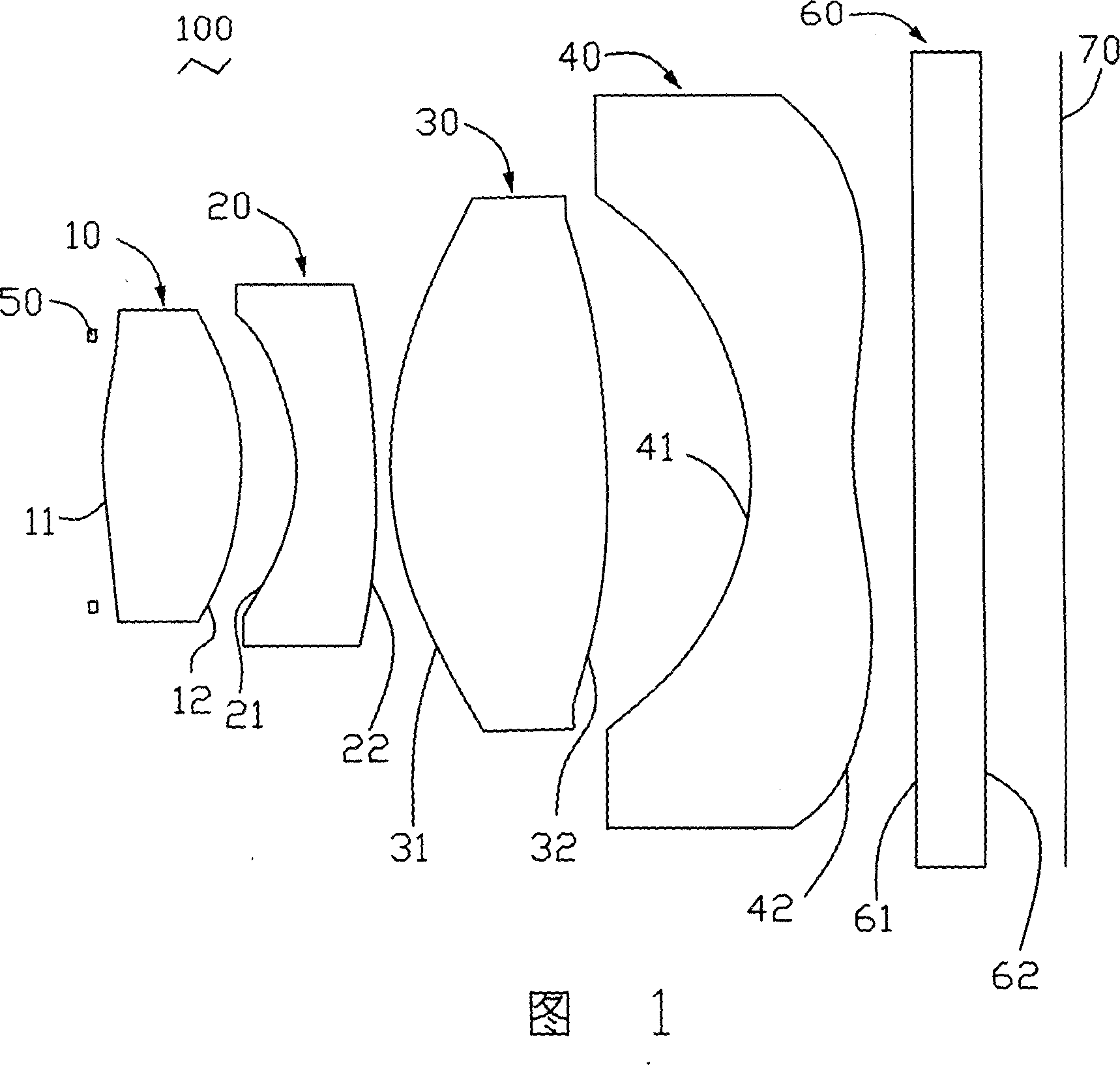
[0016] Please refer to FIG. 1 , which is a compound lens system 100 according to a specific embodiment of the present invention, including: a first lens 10 , a second lens 20 , a third lens 30 and a fourth lens 40 arranged in order from the object side to the image side . In addition, a diaphragm 50 is disposed on the object side of the first lens 10 , and a flat plate element 60 and an image sensor 70 are sequentially disposed on the image side of the fourth lens 40 .

[0017] The first lens 10 is a lens with a positive focal length, and the refractive index and dispersion are respectively n 1 = 1.58313, v 1 =59.4 glass material, the first and second surfaces 11 and 12 are convex, and the first surface 11 or the second surface 12 can be coated with an infrared cut-off film to eliminate the influence of infrared rays on the imaging quality. In this embodiment, the preferred glass material for the first lens is L-BAL42, which is scratch-resistant, abrasion-resistant, moisture...


PUM


Abstract

The compound lens system comprises: from the objective to image, a glass-made first lens, a plastic-made second / third / fourth lens. Wherein, the first and third lenses have positive focus, other lenses have negative focus; all of four lenses have aspheric surface structure. This invention has well physical performance and well imaging feature fit to be used on mobile phone.

Description

【Technical field】 [0001] The invention relates to a compound lens system, in particular to a compound lens system applicable to mobile phones. 【Background technique】 [0002] Traditional digital camera lenses can be divided into three categories: glass lenses, plastic lenses, and hybrid lenses. [0003] When applying digital camera lenses to mobile phones, it is difficult to meet the requirements of light weight and low cost due to the heavy weight and high cost of all-glass lenses. Although the all-plastic lens has the advantages of light weight and low cost, it is easily affected by the external environment, and the plastic lens in contact with the outside has poor performance in temperature resistance and scratch resistance. [0004] In the traditional glass-plastic hybrid lens, the arrangement positions of the glass lens and the plastic lens are different. In one of the glass-plastic hybrid lenses, according to the order from the object space to the image space, it inc...

Claims


Application Information

Patent Timeline
IPC IPC(8): G02B9/34
CPCG02B9/34G02B13/18G02B13/004G02B13/16
Inventor 孙文信
Owner HONG FU JIN PRECISION IND (SHENZHEN) CO LTD
Learn More