
Optical imaging device of miniature display eyepiece

An optical imaging and micro-display technology, applied in optics, optical components, magnifying glass, etc., can solve the problems of system thickness and weight, achieve the effects of simplifying the structure, improving the imaging quality, and improving the imaging quality

Active Publication Date: 2011-08-17
BYD SEMICON CO LTD
View PDF0 Cites 0 Cited by
  • Summary
  • Abstract
  • Description
  • Claims
  • Application Information

AI Technical Summary

Problems solved by technology

[0004] There are many lenses and the disadvantages of heavy system

Method used


Image

  • Optical imaging device of miniature display eyepiece
  • Optical imaging device of miniature display eyepiece
  • Optical imaging device of miniature display eyepiece

Examples


Embodiment Construction

[0029] The present invention will be further described in detail below through specific embodiments and in conjunction with the accompanying drawings.

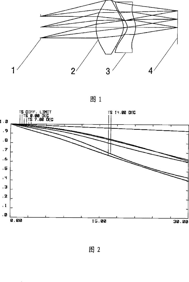
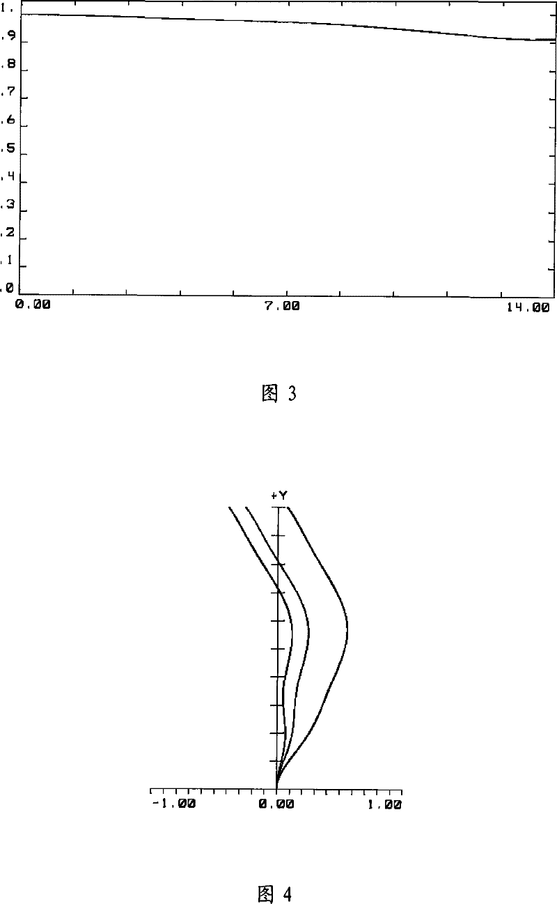
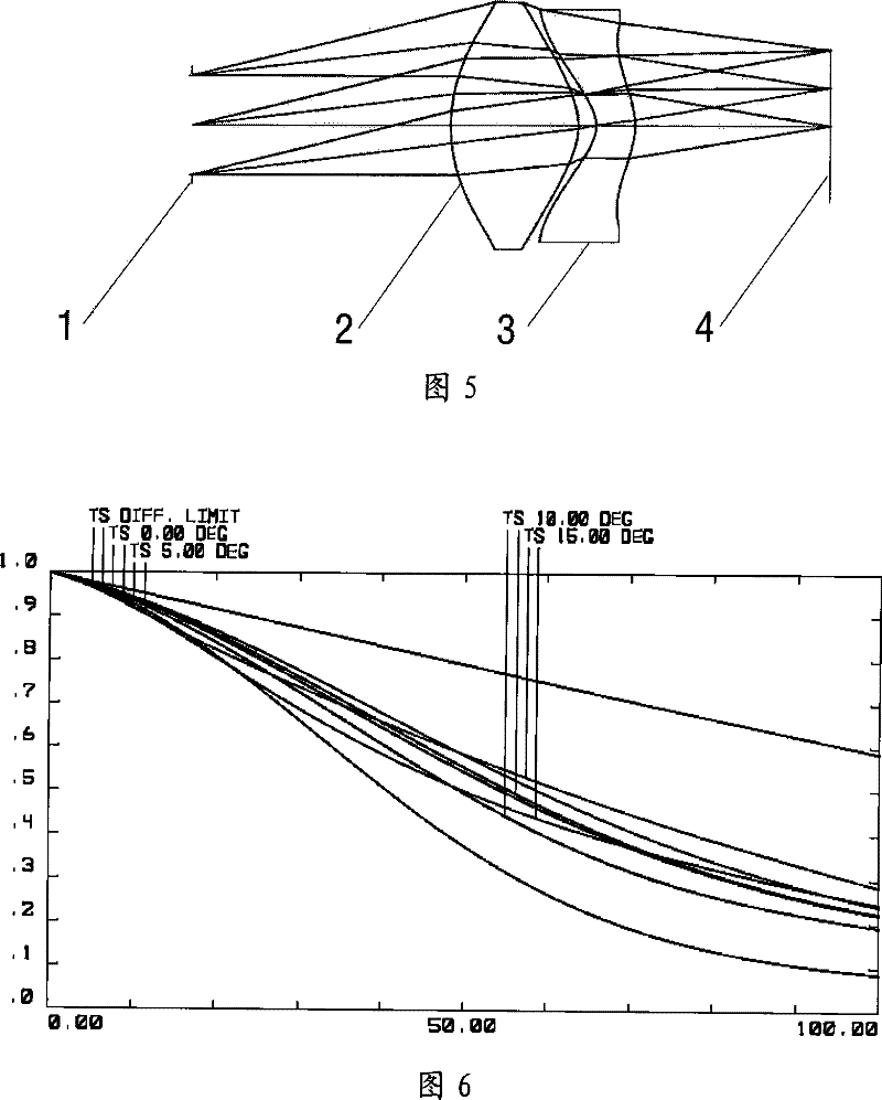
[0030] Such as Figures 1 to 12 Shown, a kind of miniature display eyepiece optical imaging device, comprises image source 4, also comprises a lens group, and this lens group is by the first lens 2 with positive diopter and the first lens 2 of positive diopter that this lens group is arranged in order from human eye to image source by common optical axis. It consists of a second lens 3 with negative diopter, wherein the first lens 2 has a first surface facing the human eye and a second surface facing the image source, the first surface protrudes toward the human eye, and the second surface faces the image One side of the source is convex; the second lens 3 has a third surface facing the human eye and a fourth surface facing the image source, the middle part of the third surface is concave relative to the human eye side, and th...


PUM


Abstract

An optical imaging device of a micro display eyepiece comprises an image source and a lens combination, the lens combination is composed of a common optical axis, a first lens and a second lens, wherein the first lens has positive diopter, the second lens has negative diopter, and the first lens and the second lens are sequentially arranged from eyes to the image source, wherein the first lens has a first surface facing the eyes and a second surface facing the image source, the first surface is convex to the side of the eyes, the second surface is convex to the side of the image source, the second lens has a third surface facing the eyes and a fourth surface facing the image source, the middle portion of the third surface is concave corresponding to the side of the eyes, the middle portion of the fourth surface is convex towards the side of the image source, and the first surface, the second surface, the third surface and the fourth surface are all non-spherical surfaces. The optical imaging device utilizes the two-piece structure of the first lens with positive diopter and the second lens with negative diopter, utilizes fewer lenses, corrects various phase differences through optimizing asphericity coefficient of the lens combination, and meets requirements of eye-protective micro display systems well.

Description

technical field [0001] The invention relates to an optical imaging system, in particular to an eye-protecting micro-display eyepiece optical imaging device. Background technique [0002] Modern visual displays mainly include eye protection type and see-through type. The eye-protecting display is to pass the image of the display through the optical system into a magnified virtual image, and the human eye can only see the virtual image formed by the pattern or signal on the display. [0003] In the field of eye protection display applications, it is always hoped that the system can have a larger field of view, eye distance (exit pupil distance) and exit pupil diameter. But at the same time to ensure the smallest possible volume and light weight. Therefore, it is difficult to satisfy the above three goals and image quality at the same time. Often the exit pupil diameter or eye distance is insufficient, or the above indicators are met, but the image quality is insufficient. ...

Claims


Application Information

Patent Timeline
Patent Type & Authority Patents(China)
IPC IPC(8): G02B25/00G02B9/10G02B27/01
Inventor 姜莉莉
Owner BYD SEMICON CO LTD
Learn More