Suction jet pump

A jet pump and suction type technology, applied in the field of suction jet pump, can solve the problem of low delivery coefficient of the suction jet pump, and achieve the effect of simple manufacture

Inactive Publication Date: 2009-03-11
CONTINENTAL AUTOMOTIVE GMBH
View PDF6 Cites 0 Cited by
  • Summary
  • Abstract
  • Description
  • Claims
  • Application Information

AI Technical Summary

Problems solved by technology

In this type of fuel tank, the problem is that at a lower filling level, fuel can no longer flow from one chamber over the saddle into the other chamber
Its disadvantage is that due to the presence of the propulsion line to the suction jet pump and the main line from the suction jet pump, two lines must be arranged and fixed in the fuel tank
The disadvantage of this embodiment is the low delivery coefficient of the suction jet pump, about 2

Method used


Image

  • Suction jet pump
  • Suction jet pump
  • Suction jet pump

Examples


Embodiment Construction

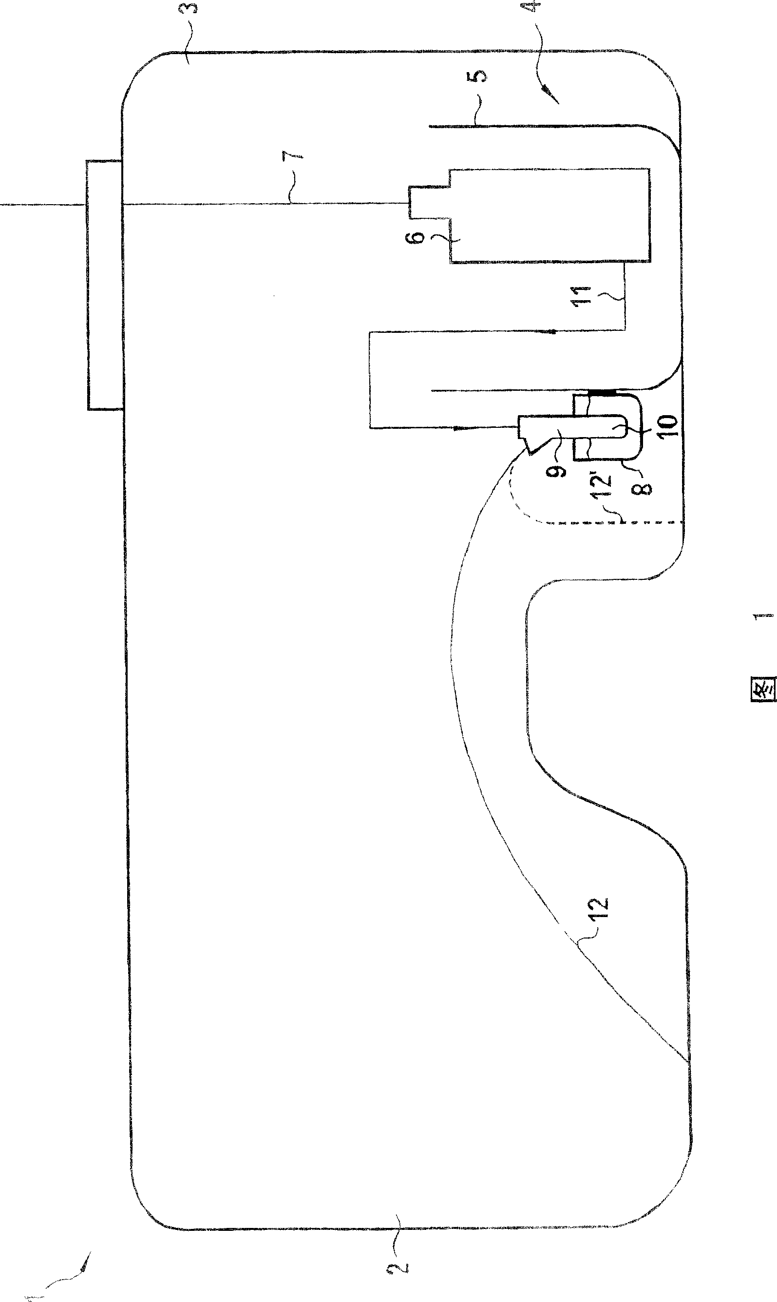
[0020] FIG. 1 shows a fuel tank 1 comprising two chambers 2 , 3 . A delivery unit 4 is fixed in the fuel tank 1 , which comprises a splash guard cylinder 5 and a fuel pump 6 arranged in the splash guard cylinder 5 . The fuel delivered by the fuel pump 6 is led to the internal combustion engine via a forward line 7 , not shown in the figure. A tank 8 is fixed to the outer wall of the splash cylinder 5 . The suction jet pump 9 is arranged relative to the tank 8 such that the mixing tube 10 of the suction jet pump 9 protrudes into said tank. Fuel is supplied from fuel pump 6 to suction jet pump 9 via line 11 . Another line 11 extends from the suction jet pump 9 into the other chamber 2 . Fuel is delivered via line 12 out of chamber 2 into chamber 3 or directly into the splash cylinder 5 .

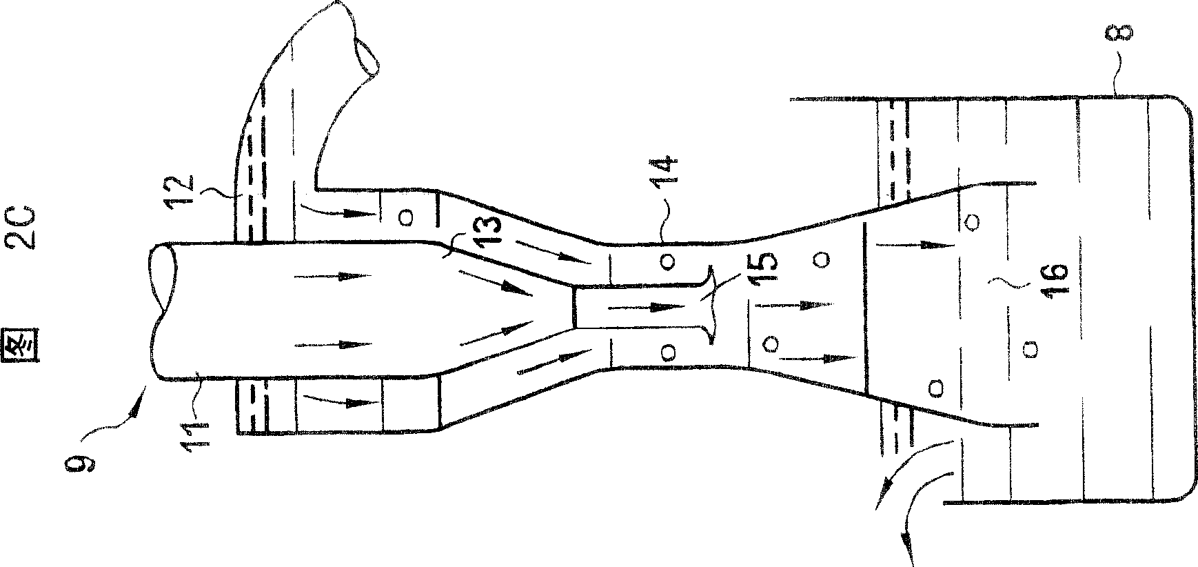
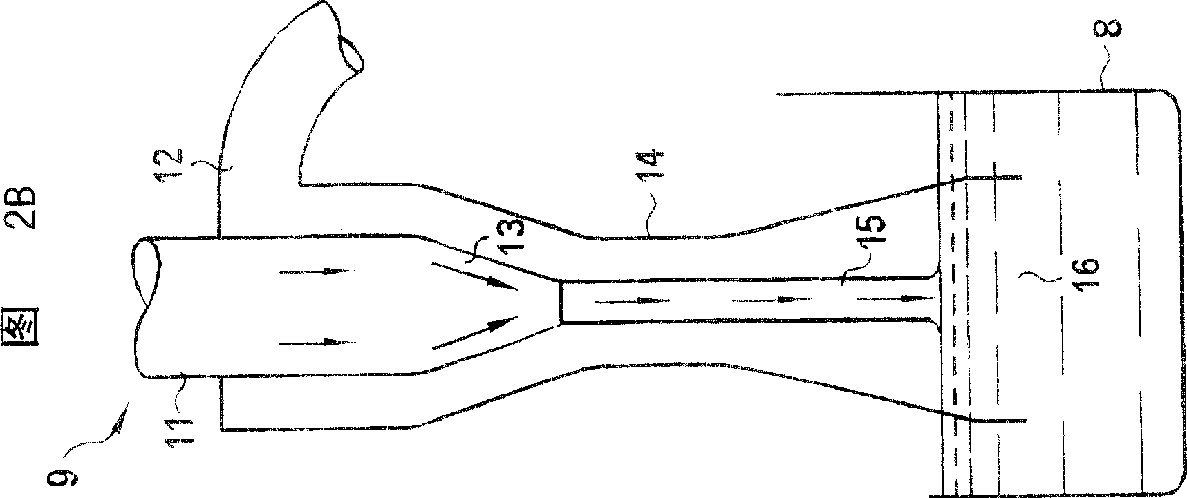
[0021] The suction jet pump 9 shown in FIGS. 2 a - c comprises a propulsion jet nozzle 13 , a mixing tube 14 , suction line 12 and a tank 8 . A propulsion jet 15 is supplied to the suctio...


PUM


Abstract

The invention relates to a suction jet pump (9) comprising a propelling jet nozzle (13), a mixing tube (14), a suction hole and a suction line (12) arranged thereon, of which at least part The mixing tube (14) is arranged in a tank (8). The suction jet pump (9) is used for supplying fuel in a fuel container (1) or from a fuel container (1) in a splash-proof cylinder (5), which is arranged inside the fuel container (1).

Description

technical field [0001] The invention relates to a suction jet pump having a propulsion jet nozzle, a mixing tube, a suction opening and a suction line connected thereto. The suction jet pump serves to deliver fuel within the fuel tank or to deliver fuel outside the fuel tank in a splash cylinder arranged within the fuel tank. Background technique [0002] Fuel tanks are known in many different forms. Since the fuel tank is adapted to the motor vehicle to utilize the existing installation space, a fuel tank which is divided into a plurality of chambers results. [0003] Most of these chambers are connected to the saddle. The problem with fuel tanks of this type is that, at lower filling levels, fuel can no longer flow from one chamber over the saddle into the other chamber. Since there is usually only one delivery unit in a fuel tank, the fuel in the other chamber cannot reach the delivery unit. In such cases, suction jet pumps are used in order to supply the delivery uni...

Claims


Application Information

Patent Timeline
Patent Type & Authority Patents(China)
IPC IPC(8): F02M37/02F04F5/02F02M37/00F02M37/10F02M37/18F04F5/10F04F5/44F04F5/54
CPCF02M37/106F02M37/025F04F5/44F04F5/54F04F5/10Y10T137/86075F04F5/02F02M37/02
Inventor M·泰歇尔特K·基宁格尔
Owner CONTINENTAL AUTOMOTIVE GMBH
Why Eureka
Try Eureka