
An apparatus for radiating one surface

A technology for irradiation devices and rays, which is applied in the direction of laser devices, semiconductor laser devices, lasers, etc., can solve the problems of poor collimation of laser rays, poor collimation of slow axis, etc., achieve high intensity and improve collimation , Improve the effect of applicability

Active Publication Date: 2009-03-04
LIMO GMBH
View PDF5 Cites 0 Cited by
  • Summary
  • Abstract
  • Description
  • Claims
  • Application Information

AI Technical Summary

Problems solved by technology

In addition, this ray converter is arranged so close to the semiconductor laser rod that the light rays from the emitters do not overlap each other before entering the ray converter. This enables the possibility that the slow axis collimator is A relatively large distance setting from the semiconductor laser rod, thus achieving a large beam spread in the direction of the slow axis, it is still possible to achieve a small divergence in the direction of the slow axis and also achieve a good collimability. This structure is currently not possible in QCW rods, so the collimation of the laser rays emitted from QCW rods is very poor.
[0003] Furthermore, it has been found that when using a semiconductor laser rod for irradiating a surface or for operating a free irradiator, the different divergence of the fast axis and the slow axis and the poor collimability of the slow axis are disadvantageous

Method used


Image

  • An apparatus for radiating one surface
  • An apparatus for radiating one surface
  • An apparatus for radiating one surface

Examples


Embodiment Construction

[0023] In the drawings, for the sake of greater clarity, a Cartesian coordinate system is used.

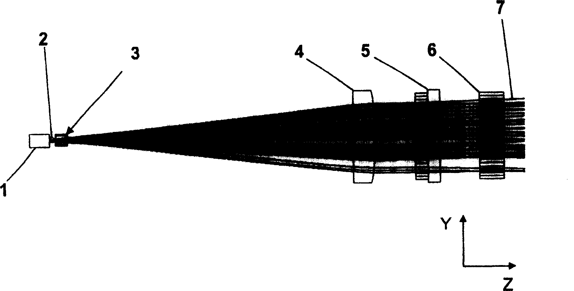
[0024] Such as Figure 1a with 1b As shown, a device according to the invention comprises a semiconductor laser rod 1, which in particular consists of a so-called QCW rod. Like other semiconductor laser rods, a QCW rod also has many emitters arranged side by side in the X direction and spaced apart from each other. In QCW rods, however, the distance between the individual emitters is significantly smaller than the extent of the emitters in the X direction.

[0025] In a typical QCW rod, for example 60 emitters are arranged side by side and spaced apart from each other in the X direction, the so-called slow axis direction. The dimension of the radiating face of the emitter in the Y direction, the direction of the so-called fast axis, may be approximately 1 μm and in the X direction approximately 150 μm. The distance between the individual emitters can be approximately 10 μm in t...


PUM


Abstract

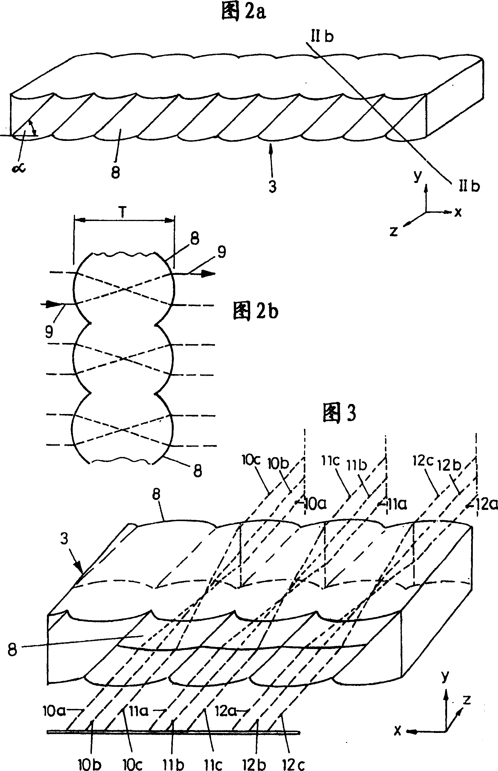
A device for illuminating a surface comprising at least one semiconductor laser rod (1) having a plurality of emitters, wherein the distance between the emitters is smaller than the extent of the emitters in a first direction (X); further comprising Ray converters (3) for converting laser beams emitted from the emitter are constructed such that they diverge the laser beams in a first direction (X) and in a second direction (Y) Divergent exchange on the beam converter (3), wherein the beam converter (3) has such a distance from the laser diode bar (1) that the laser beams of at least two adjacent emitters hit the beam converter (3) at superimposed on each other in the first direction (X).

Description

technical field [0001] The invention relates to a device for irradiating a surface, which device comprises at least one semiconductor laser bar (Halbleiterlaser barren), which has a plurality of emitters (Emittern), which are arranged side by side and at a distance from each other in a first direction, wherein the distance of the emitters from one another is smaller than the extent of the emitters in a first direction and wherein the divergence of the laser beam emitted from the emitters in the first direction is smaller than in a second direction perpendicular to the first direction divergence, the device also includes a collimator for at least partially collimating the laser rays emitted from the emitter. Background technique [0002] Devices of the above-mentioned type have been known for a long time. Semiconductor laser rods with very small distances between the individual emitters are usually composed of QCW rods, which can be operated quasi-continuously. In semiconduc...

Claims


Application Information

Patent Timeline
Patent Type & Authority Patents(China)
IPC IPC(8): G02B27/09G02B27/30G02F1/35H01S5/40H01S3/00
CPCG02B27/0922G02B19/0057G02B27/0966H01S5/4012H01S5/4025G02B19/0014G02B27/30G02B27/00
Inventor T·米特拉J·迈因席恩W·希尔
Owner LIMO GMBH
Learn More