
An electric kettle and a mounting method thereof

An installation method and technology for electric heating cookware, which can be applied to household appliances, kitchen utensils, water-boiling utensils, etc., and can solve problems such as mechanical damage and appearance deterioration.

Inactive Publication Date: 2009-03-04
BOSCH SIEMENS HAUSGERATE GMBH
View PDF5 Cites 0 Cited by
  • Summary
  • Abstract
  • Description
  • Claims
  • Application Information

AI Technical Summary

Problems solved by technology

This compaction can lead to bending stresses on the circumference of the jug which, in the case of fragile materials, can cause cosmetic deterioration and mechanical damage over time

Method used


Image

  • An electric kettle and a mounting method thereof
  • An electric kettle and a mounting method thereof
  • An electric kettle and a mounting method thereof

Examples


Embodiment Construction

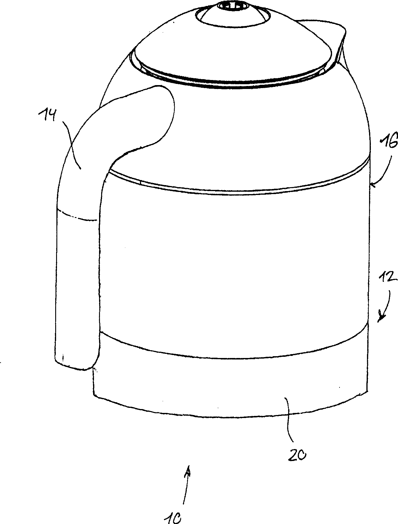
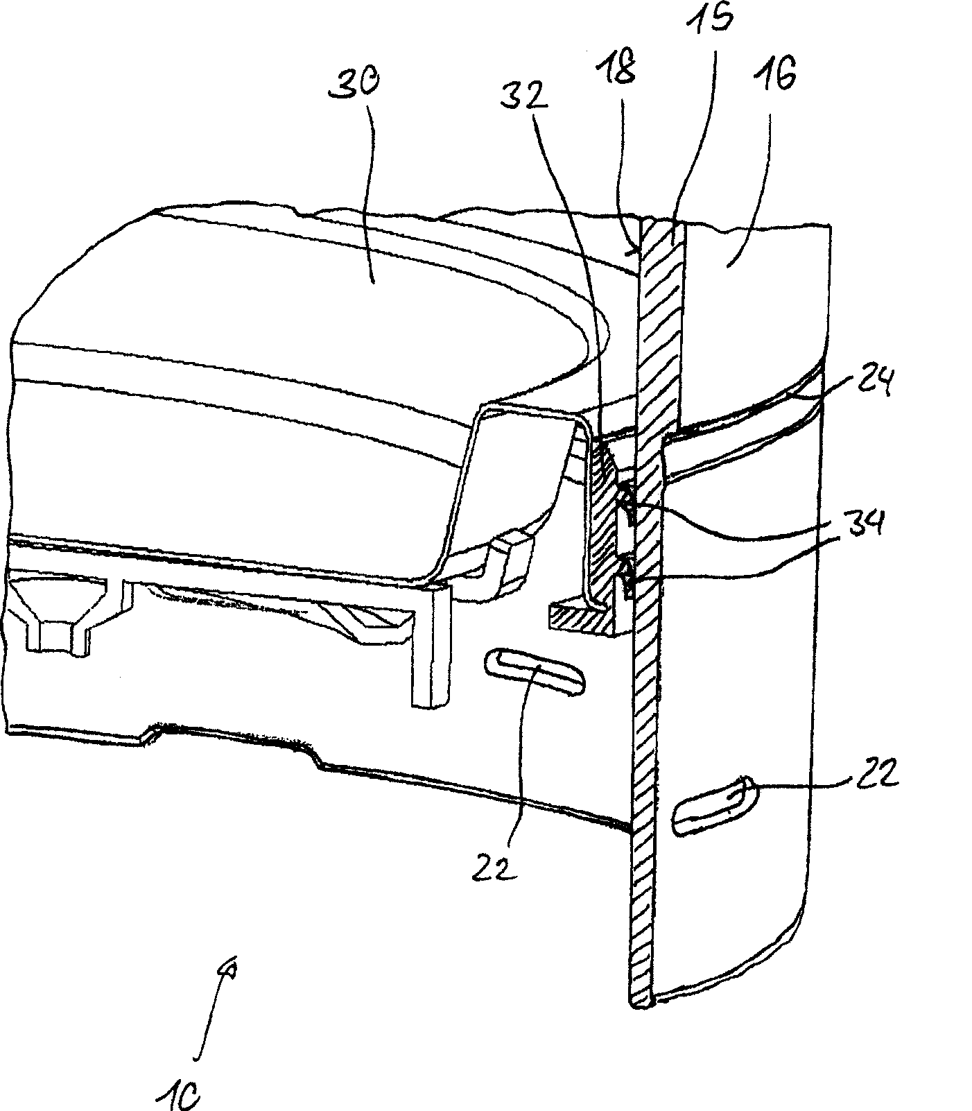
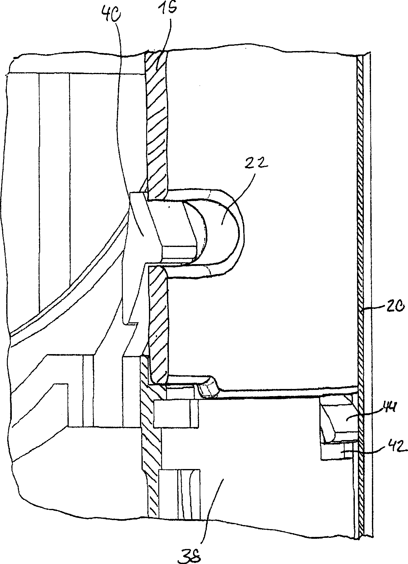
[0020] figure 1 The schematic diagram of represents an electric cooker. It comprises a jug-shaped plastic cooking vessel 10 , in which an electrically energized heating mechanism is arranged in a base area 12 , which can be connected to the cooking vessel, in particular by means of a vessel base. Below, combine Figure 2-4 The cutaway diagram of the diagram shows the layout of the heating mechanism and the bottom plate of the vessel. The cooking vessel 10 has a handle 14 , which is fastened to the outer surface 16 and is used for handling the cooking vessel 10 , in particular to pour out liquid heated in the vessel.

[0021] In addition, a shroud 20 is provided in the bottom region 12, which may be part of the container foot and which is preferably made of sheet metal, such as aluminum or special steel. In the exemplary embodiment shown, the shroud 20 is flush with the outer peripheral surface 16 of the cooking vessel 10 . The shroud 20 is preferably connected to the outer...


PUM


Abstract

The covering ring (20) is held against a resilient component (44) by friction at the outer casing surface (16) of the cooking vessel (10). An independent claim is included for the corresponding method of assembly of the electrically-heated cooking vessel.

Description

technical field [0001] The invention relates to an electric heating cooker and an installation method of the electric heating cooker. Background technique [0002] Electric cooking utensils, such as electric kettles, usually have a metal covering ring on the bottom of the outer peripheral surface, and the covering ring is installed to cover the connection point connected to the bottom plate of the vessel and / or for artistic modeling or design considerations. Typically, the shroud made of a special steel or aluminum sheet is screwed or snapped onto the outer circumference of the cooking vessel, or is also clamped by means of the vessel base. As the cookware heats up during the heating of the heating element, it generally expands to a greater extent than the shroud because the cookware is plastic and thus has a different coefficient of thermal expansion than the metal shroud. [0003] The connection of the cooking utensil to the base of the utensil should exert as little bend...

Claims


Application Information

Patent Timeline
Patent Type & Authority Patents(China)
IPC IPC(8): A47J27/21
CPCA47J27/21166A47J27/21041
Inventor K·西蒙M·理查德S·迈克尔
Owner BOSCH SIEMENS HAUSGERATE GMBH
Learn More