Image device, image processing system and method thereof
An image processing and image technology, applied in image communication, television, electrical components, etc., can solve the problems of low image quality, low bit transmission rate of compressed images, etc., and achieve the effect of reducing the number of pictures
- Summary
- Abstract
- Description
- Claims
- Application Information
AI Technical Summary
Problems solved by technology
Method used
Image
Examples
Embodiment approach
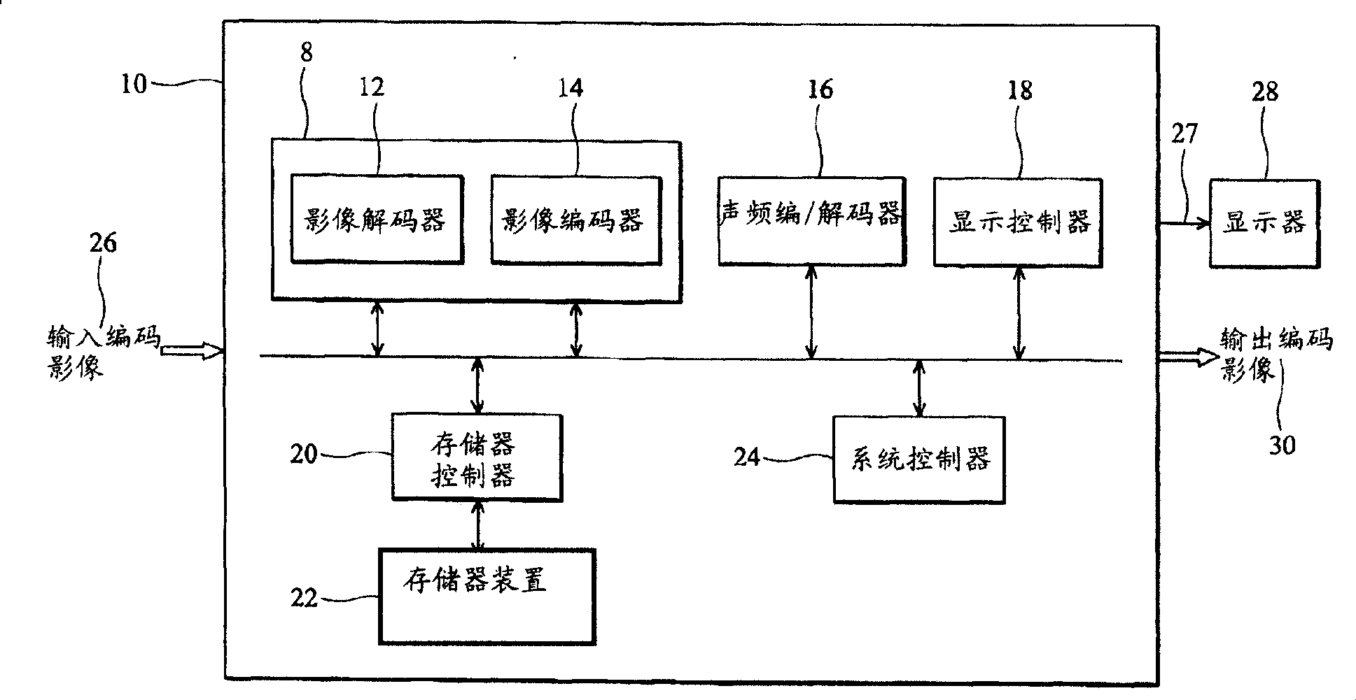
[0038] refer to figure 1 , the video controller 10 includes a video codec (video codec) 8 , a display controller 18 and a memory device 22 . The video codec 8 includes a video decoder 12 and a video encoder 14 . Image controller 10 receives input encoded image 26 and generates output encoded image 30 . The input encoded image 26 and the output encoded image 30 may be transmitted as a continuous bit stream. The input coded image 26 and the output coded image 30 may have frames coded according to different compression algorithms, and different compression algorithms have different compression ratios or resolutions. Display controller 18 generates video signal 27 for display 28 . Each image 26 and 30 includes consecutive frames. During frame decoding, encoding, and display, certain frames are temporarily stored in memory device 22 . The video decoder 12, the video encoder 14, and the display controller 18 share the memory device 22, so that the number of frames that must be ...
no. 1 approach
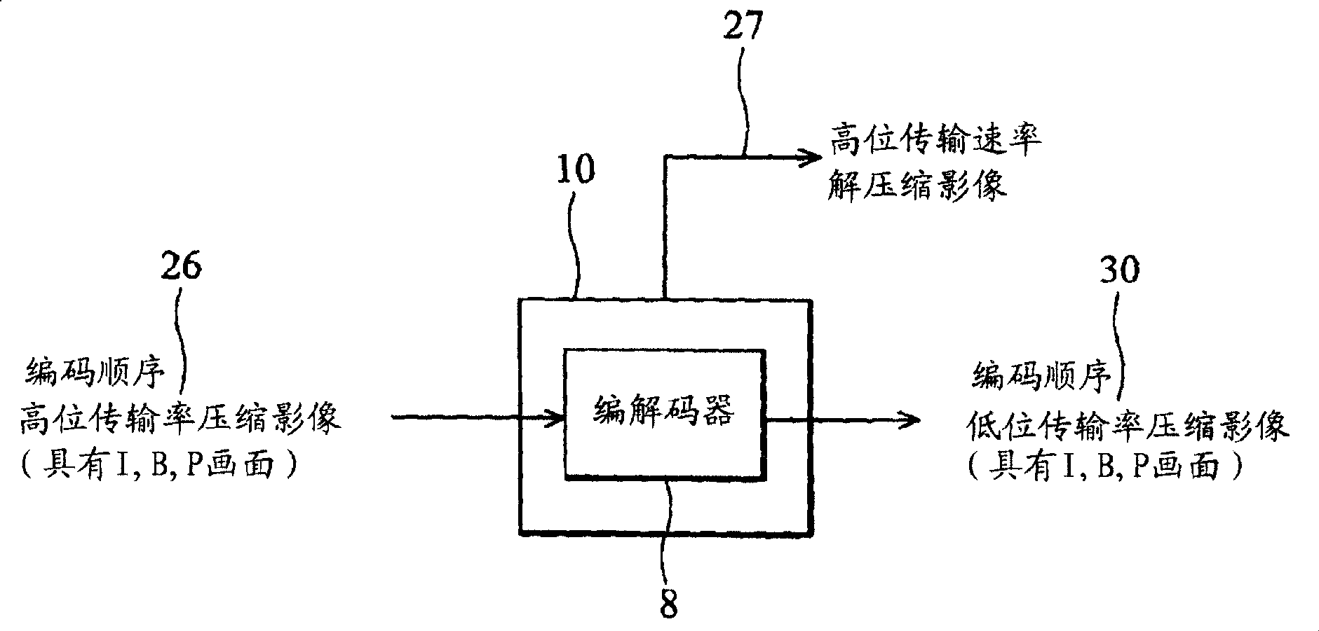
[0043] refer to Figure 2A , in the first embodiment, the input encoded image 26 at the input end is a high bit rate compressed image, and the output encoded image 30 at the output end is a low bit rate compressed image. The input coded image 26 has the same resolution as the output code 30 . Both the input encoded image 26 and the output encoded image 30 have frames sorted in encoding order. Display controller 18 transmits the decompressed frames to display 28 with a high bit rate and sorted in display order. The image controller 10 outputs a compressed image 30 with a low bit rate (eg, for storage), while the display 28 displays a decompressed image with a high bit rate. The frames of the input encoded image 26 and the output encoded image 30 may be encoded according to the MPEG standard.
[0044] Higher bit-rate compressed video has a higher bit rate than lower bit-rate compressed video, while high bit-rate decompressed video ) has a higher bit rate than lower bit-rate ...
no. 2 approach
[0067] In the second embodiment, the low-bit-rate compressed image 30 has a lower resolution than the high-bit-rate compressed image 26 . Compressed images 26 and 30 may have the same or different compression ratios (eg, quantization levels). For example, the input encoded image 26 may have a resolution of 1920*1080, while the output encoded image 30 may have a resolution of 1366*768. The encoded images 26 and 30 are frames sorted in encoding order. The display controller 18 transmits the high resolution frames sorted in display order to the display 28 . Therefore, the image controller 10 outputs the low-bit-rate compressed image 30 with low resolution while displaying the high-resolution image on the display 28 .
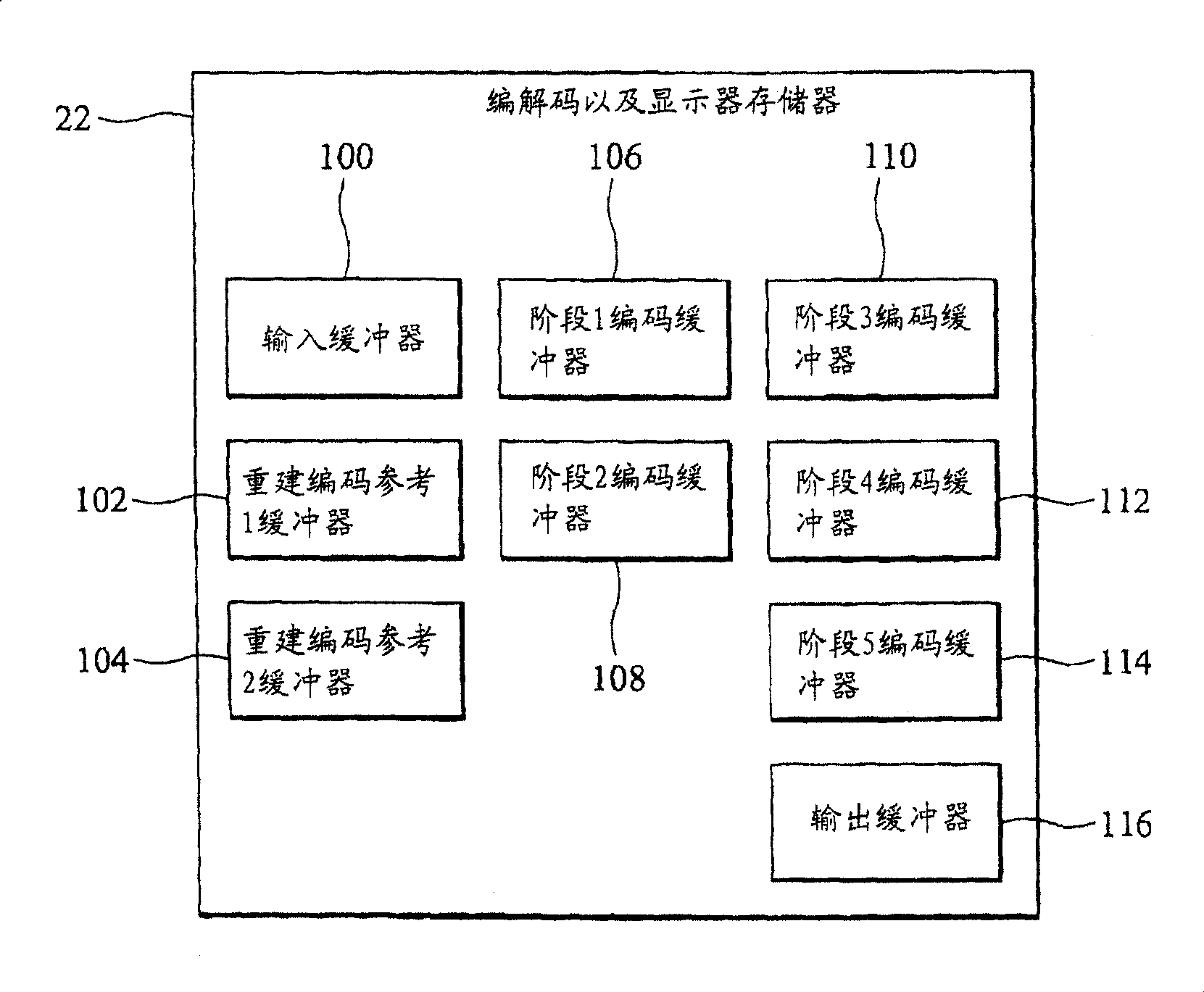
[0068] like Figure 2B As shown, the arrangement of the memory buffer in the memory device 22 in the second embodiment is the same as that in the first embodiment. The input buffer 100 stores high-resolution compressed frames, and the output buffer 116 stores l...
PUM
 Abstract
Description
Claims
Application Information
 - R&D
- Intellectual Property
- Life Sciences
- Materials
- Tech Scout
- Unparalleled Data Quality
- Higher Quality Content
- 60% Fewer Hallucinations
Browse by: Latest US Patents, China's latest patents, Technical Efficacy Thesaurus, Application Domain, Technology Topic, Popular Technical Reports.
© 2025 PatSnap. All rights reserved.Legal|Privacy policy|Modern Slavery Act Transparency Statement|Sitemap|About US| Contact US: help@patsnap.com


