Systematic balance stable-flow valve

A system balance, steady flow valve technology, applied in lift valve, multi-port valve, valve device and other directions, can solve problems such as affecting the measurement accuracy of the meter and damage to the measurement electrode.

Inactive Publication Date: 2009-02-04
SUZHOU ZHONGXIN POWER POLYTRON TECH
View PDF6 Cites 0 Cited by
  • Summary
  • Abstract
  • Description
  • Claims
  • Application Information

AI Technical Summary

Problems solved by technology

[0006] The present invention provides a system balance steady flow valve in order to solve the technical problems in the prior art that sampling personnel and other irrelevant personnel can adjust the flow at will, affect the measurement accuracy of the meter and cause damage to the measurement electrode.

Method used


Image

  • Systematic balance stable-flow valve
  • Systematic balance stable-flow valve
  • Systematic balance stable-flow valve

Examples


Embodiment Construction

[0029] The present invention will be further described below in conjunction with accompanying drawing and embodiment:

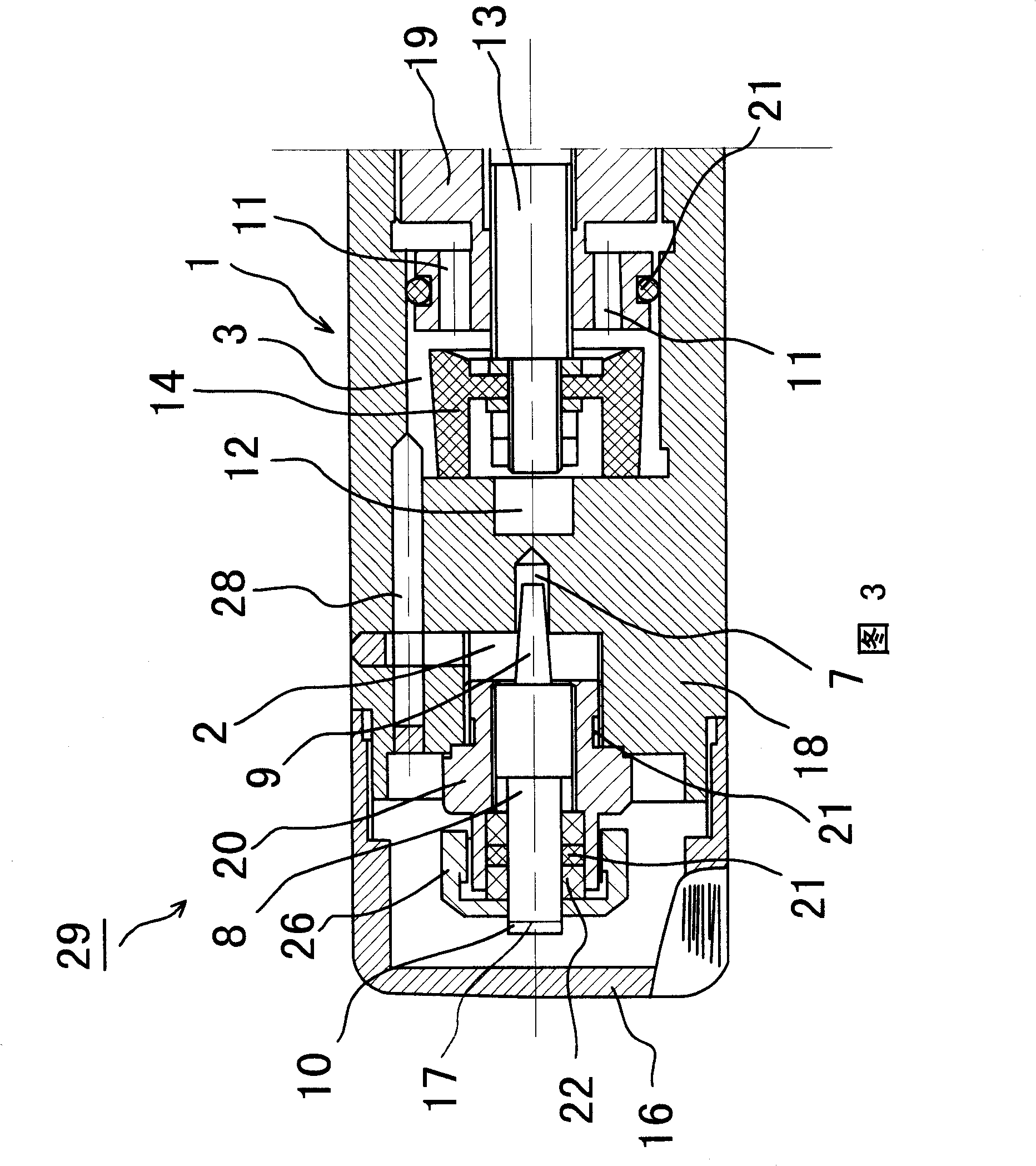
[0030] Embodiment: Referring to Figures 2 to 4, a system balance steady flow valve includes a valve seat 1, the valve seat 1 is composed of a valve body 18 in the middle and valve covers 19, 20 at the front and rear ends. The valve seat 1 is provided with a first valve chamber 2 , a second valve chamber 3 , a sample water inlet 4 , a sampling outlet 5 and a discharge outlet 6 . The valve body 18 is cylindrical, the first valve cavity 2 is a circular groove opened on the rear end of the valve body 18 , and the second valve cavity 3 is a circular groove opened on the front end of the valve body 18 . The valve cover 19 is embedded in the front end of the valve body 18 to close the second valve chamber 3, and the valve cover 19 is sealed with the valve body 18 by an O-ring 21. The valve cover 20 is embedded in the rear end of the valve body 18 to seal the first v...


PUM


Abstract

The present invention relates to a system balancing flow stabilizing valve in a thermal power plant water vapor sampling apparatus, which is characterized in that it includes a valve seat on which disposed a first valve cavity, a second valve cavity, a sample water inlet, a sampling outlet and an abandon outlet; one end of the first valve cavity is disposed with a hole shape valve port connected to the sample water inlet, another side connects the inlet of the second valve cavity; the head part of a needle type valve spindle is inserted in to the hole shape valve port to form an adjusting valve core, the end of the adjusting valve core is as an operation part which is covered by a cover; one end surface in axial direction of the second valve cavity is disposed with a sampling passage end port connected to the sampling outlet, another end surface is disposed with an abandon passage end port connected to the abandon outlet; the front and rear end surfaces of a block of the head part of a diffluence adjusting valve rod cooperate with the sampling passage end port and the abandon passage port to form a diffluence adjusting valve core. The invention combines an adjusting valve with a diffluence adjusting valve in series, hides the operation part of the adjusting valve in order to prevent that the sampling person and irrelevant person can adjust the flux by themselves and ensure the stability and balance of the flux of the end path of the system.

Description

technical field [0001] The invention relates to a special valve in a water vapor sampling device system of a thermal power plant, in particular to a valve used to control the manual sampling flow at the end of a thermal power plant in a water vapor sampling device system. Background technique [0002] The current thermal power plants first use the boiler to generate steam, and then use the steam to drive the steam turbine to drive the generator set to generate electricity. The boiler and steam system used in it are all working 24 hours a day all year round. In order to ensure the operation of the boiler and steam system Safety requires real-time detection of various water sample indicators in the boiler and steam system, such as water at the outlet of the condensate pump, water at the outlet of the deaerator, water at the outlet of the economizer, drum boiler water, saturated steam, superheated steam A series of water vapor conductivity, oxygen content, pH, phosphate content...

Claims


Application Information

Patent Timeline
Patent Type & Authority Patents(China)
IPC IPC(8): F16K1/00F16K11/044G01N1/10
Inventor 徐中飞
Owner SUZHOU ZHONGXIN POWER POLYTRON TECH
Why Eureka
Try Eureka